its to Ugly to make Portraits, ((o; But its exact like the Pinout / Schema Connected.
I Built 6 Devices, all with Mate Gold & Silver, since i use BlueSmiRF, the System is not longer working, possible to Build / Work Correct!
The Code is my Code.
I also pay for the Code-Calculation part, for calculation of swiss Coordinates LV 95.
Cant publish the Code here!
Dont want to “lost” it.
Thank you, Michael
OK Michael,
That is as much help as I can give you.
Good luck with your project,
Paul
Is it Possible to give the code direct to you, not here Online?
im now at this Point…
(o;
Thank you for your Help, Michael
You are welcome Michael,
I can only help you openly. That way the whole SparkFun community benefits and is able to learn. If you need to keep your code closed source, I understand, but I can not help.
Best,
Paul

Above, you show the BlueSMiRF attached to 3.3V. Please try powering the BlueSMiRF with a 5V source. I believe we discovered on another post that the BlueSMiRF v2 may need 5V power in order to work correctly.
Hello Sparky,
Sparkfun 15136 connected via UART2 to BlueSMiRF v2 ist not ok? No 5V?
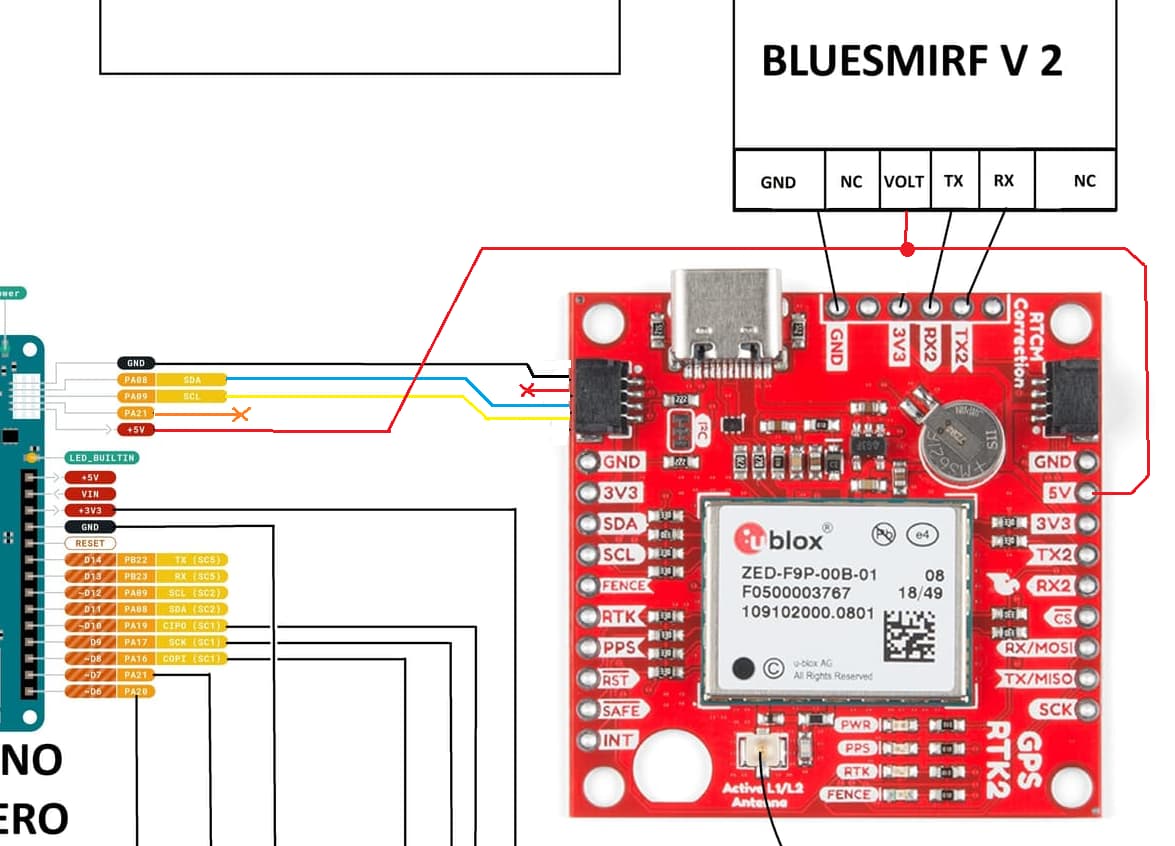
PAULZC : make it exact the same https://canada1.discourse-cdn.com/sparkfun/original/2X/9/93cfb2340df718b82f690766a9686e320acecfe7.jpeg
In your Hookup Guide its Written 3,3V -5V!
Hardware Overview - SparkFun BlueSMiRF v2 Hookup Guide
Or is this wrong?
Thank you very much, Michael
Hmm, 3.3V works just fine. I’m sorry, but I can’t replicate your issue.

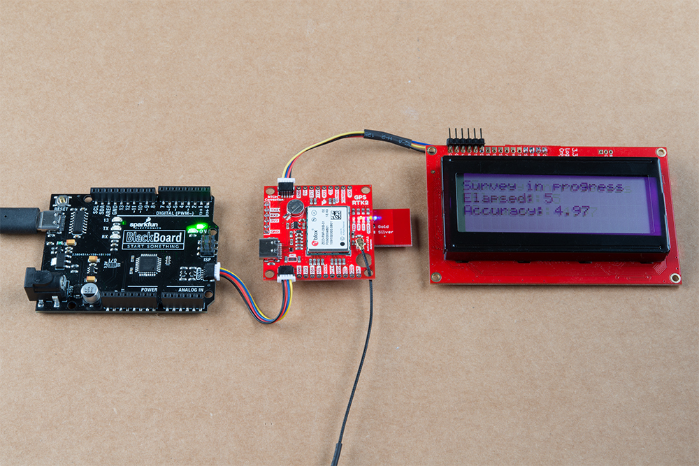
Above is the ZED-F9P attached to the BlueSMiRF. An ESP32 is connected over a Qwiic cable, only for power. The ZED is connected to a ~30mA external antenna.

ZED-F9P is running v1.13 firmware, and UART2 is configured for output of NMEA+UBX+RTCM at 115200.

Above, I then confirm the ZED is outputting NMEA using Bluetooth Serial App.

Above, I then disconnect Bluetooth Serial App and use SW Maps to connect to the BlueSMiRF v2. I connect to the local NTRIP Caster/Server for corrections, which are then sent over the Bluetooth connection. Within a few seconds, I have RTK Fix.

Note in the above pictures, I am powering the ZED and BlueSMiRF only over I2C for worst case scenario. The voltage at the first Qwiic connector on the ESP32 (used only for power) is 3.3.V. The voltage then at the ZED-F9P breakout is 3.15V, so some drop. Checking the voltage on the BlueSMiRF, beyond the 3.3V regulator, is 3.10V, so some further drop in voltage.

Above, connecting back to the ZED over USB, with SW Maps connected over Bluetooth with corrections being sent over Bluetooth, we can see the RTCM count increasing on the ZED indicating it is getting corrections.
The BlueSMiRF is operating correctly and doing everything it was designed to do, even down to ~3.0V.
I understand the original BlueSMiRFs work, but the v2 does not in your project. All I can say is that our hardware seems to be performing as designed, and we are really at a loss as to what may be causing your problem. Power ripple? Noise in your system? It’s hard to say at this point.
1 Like
Hy Sparky,
the last configuration was:
Protocol IN 0+1+5 UBX + NMEA + RTCM3
Protocol OUT 0+1+5 UBX + NMEA + RTCM3
115200
Firmware Updated to 1.51
all the same like PAULZC
Thank you very much, Michael
Last Night i unconnect BlueSMiRF v2, and connect Bluetooth Mate Gold from an old Device.
Result = 100% Accuracy

How we must Configurate BlueSMiRF v2 that it can do EXACT the same as Bluetooth Mate Gold & Silver do?
You have Replace it, but not 100% with the same Configuration!
You Write, its work Perfect in US, but not in Swiss, so its maybe something with Swiss RTK
“swipos-GIS/GEO VRS-Daten im RTCM-Format 3.1 und RTCM 3.2 MSM4 Daten im RINEX-Format” ?
Thank you very much, Michael
Hi Michael,
We have already given you a lot of help.
The key issue is that the ZED-F9P UART2 RX byte count is zero. It is not receiving data from the BlueSMiRF. You need to work out why that is happening.
I can not explain why the Mate Gold works for you, and the BlueSMiRF v2 does not. But both myself and Sparky have proven to you that the BlueSMiRF v2 works well, passing both NMEA and RTCM over Bluetooth to/from the ZED-F9P.
We have asked you several times to share a photo of the wiring around the F9P and the BlueSMiRF. It would help a lot. But you have refused to do that.
We have asked you to share your code. You aren’t willing to do that either.
Looking at the MKR Zero, the 5-pin connector is outputting 5V not 3.3V:


If your schematic is correct, then it looks like you are feeding 5V from the MKR Zero into the ZED-F9P Qwiic connector?

The Qwiic connector expects 3.3V, not 5V. 5V will damage the ZED-F9P. You should be doing one of two things:
- Feed 3.3V from the MKR Zero to the ZED-F9P and the BlueSMiRF v2,
- Or, feed 5V from the MKR Zero to the 5V breakout pad on the ZED-F9P and the V pin on the BlueSMiRF. The BlueSMiRF V pin is 5V-tolerant.
With this, I believe we have given you as much help as we can.
Best,
Paul
What im Doing Different than your Tutorial Pic:
https://cdn.sparkfun.com/assets/learn_tutorials/8/5/6/SparkFun_GPS-RTK2_Board_-_BaseStation_with_LCD.jpg ?
The System works perfect with Mate Gold, it cant be wrong wired.
Voltage or Software seems to be the Problem.
I will test the 3,3v Powering.
Can i let the rest of the Qwiic cables connected?
Only cut 5V, and connect with 3,3Volt?
Thank you very much for all your very frendly Help!
Michael
The BlackBoard in the tutorial photo has a true Qwiic connector. It is 4-pin and outputs 3.3V.
The connector on the MKR Zero is 5-pin and outputs 5V power. The SDA and SCL signals are 3.3V.
You can do one of two things:
- Feed 3.3V from the MKR Zero to the ZED-F9P and the BlueSMiRF v2
- Or, feed 5V from the MKR Zero to the 5V breakout pad on the ZED-F9P and the V pin on the BlueSMiRF. The BlueSMiRF V pin is 5V-tolerant.
The second option is actually the best one. Then you are using the 5V->3.3V regulators on both the ZED-F9P board and the BlueSMiRF v2.
There may also be a problem with the way you are powering the MKR Zero, through the battery connector.
Looking at your schematic, you are feeding 5V from a 78R05 regulator into the MKR Zero battery connector:
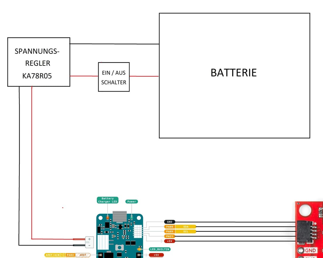
Looking at the MKR Zero schematic, there seems to be no direct path from BATT+ back to +5V:

So, the 5V pin on the 5-pin connector may not be providing 5V at all. It looks like 5V is only available when VUSB or VIN are connected. Not when the board is powered only from the LiPo connector.
It would be better to power the MKR Zero through the VIN pad:
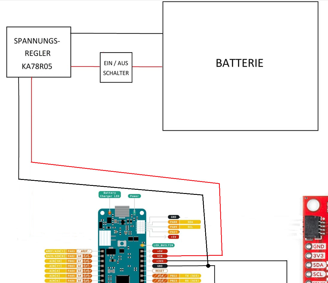
Yes sorry again, the Schema is wrong!
here the corrected version, like its really connected
I Power the MKR Zero also via VIN ! (o:
And now, Connect 15136 via MKR`s 3,3 Volt Connector
Aaaaaaaaaaaaaand HALLELUJA !!! with 3,3 Volt, the System works Perfekt!
Accuracy is Maximum 14.10mm ! ! !
Maybe this 3,3Volt Issue can be added to the Tutorial ?
Thank you very very much for your BIG Help!
Michael
1 Like
Hi Michael,
Fantastic! I am really happy it is working.
I wonder if the BlueSMiRF v2 draws slightly more current that the original Bluetooth Mate. Maybe your original power wiring was just OK for the Mate, but not OK for BlueSMiRF v2?
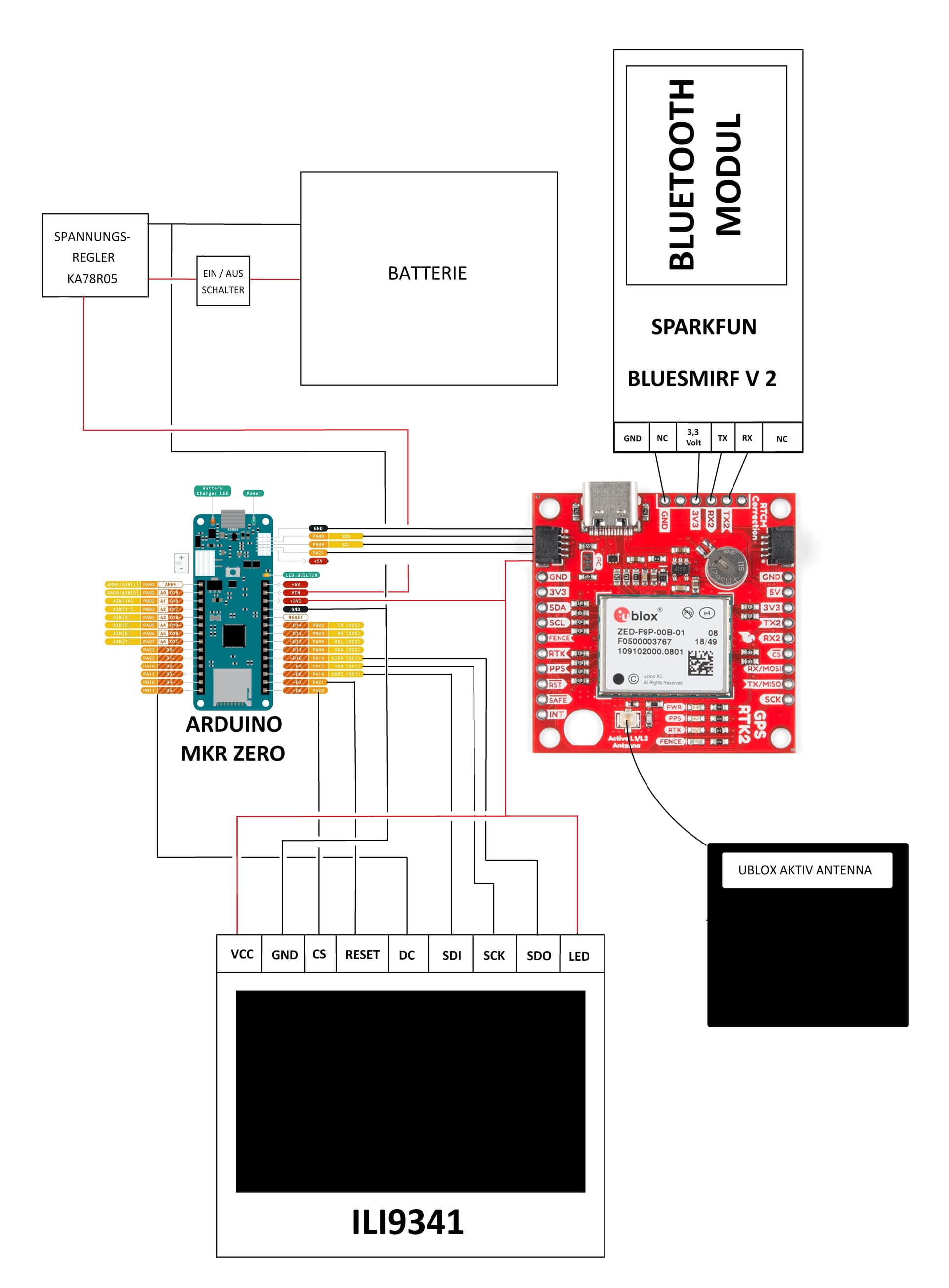
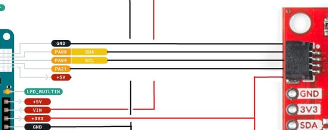
If you want your schematic to be truly accurate, I think you need to change the 5-pin connections - again:
I do not think PA21 is connected? I think you should remove that wire?
The Qwiic connector pins are:
- From top to bottom:
- GND
- 3V3
- SDA
- SCL
Maybe you should move the 3V3 wire ‘up’, showing which pin it connects to?
Best,
Paul
1 Like
Hello Paul,
Yes, P21 is Not Connected!
I must correct this also in the Schema… (o;
Thank you very much Paul!!
Michael
1 Like