Great, well done ![]()
Yes please detailed instructions, I think its important for several users here.
Great, well done ![]()
Yes please detailed instructions, I think its important for several users here.
Steps for flashing the ATTiny84 on Sparkfun Qwiic RFID board using Arduino Mega 2560 R3 as programmer:
The spi clock needs to be slower for the ATTiny84. You can even find this recommendation in the original unedited Arduino code line 49. In line 53, make this edit:
#define SPI_CLOCK (128000 / 6)
Assign the following pins because they are used to program other boards. I found this here: https://support.arduino.cc/hc/en-us/articles/4841602539164-Burn-the-bootloader-on-UNO-Mega-and-classic-Nano-using-another-Arduino#ide
The pin numbers are different for different Arduino boards so use the table in the above link to pick out the right pin numbers. If you are using Arduino mega 2560 like me, the modifications will be the following three pins:
#define ARDUINOISP_PIN_MOSI 51
#define ARDUINOISP_PIN_MISO 50
#define ARDUINOISP_PIN_SCK 52
Awesome, thank you!
I will try asap, but might take a few days before I have a Mega here.
you can use any arduino controller. go to the breakout pin diagram and identify the pins that can be used for programming other boards and make the pin changes in the code. and one more thing, if you prefer not to solder wires onto the Sparfun qwiic board, you can just use male-to-male dupont wires. I added a very thing layer of soldering wire on one end of the dupont wires to make them thick enough that they go through the qwiic board and hold tight. Once you have these wires and connections, you can flash one sparkfun board after another and it makes the process very quick (no pun intended).
Great to have a “how to” for other users facing this problem.
The only thing I think is missing, is that you probably also have to install the ATtiny core files, so you’re actually able to select the ATtiny when you want to upload the code.
yes that is required.
I think this tutorial is what finally helped me to get things working: https://www.youtube.com/watch?v=gXXdoeu7yWw
This one is also pretty good (and more recent): https://www.youtube.com/watch?v=sycSdI49hlY
Excellent work! We’re isolating and testing stock now, but happy to hear you got it going ![]()
Hello! Thank you @paulvha for identifying a classic array memory problem, and for providing the fix. I have tested it here in the office and have put it into the Firmware folder within its’ repository.
We will be getting this fix into any of the boards we have in our inventory, and for future builds.
Cheers,
Elias
Hi @happy_kass and @paulvha thank you again for your support.
I successfully flashed the ATTiny, now the NFC Reader works.
Some additional info for anyone else coming here:
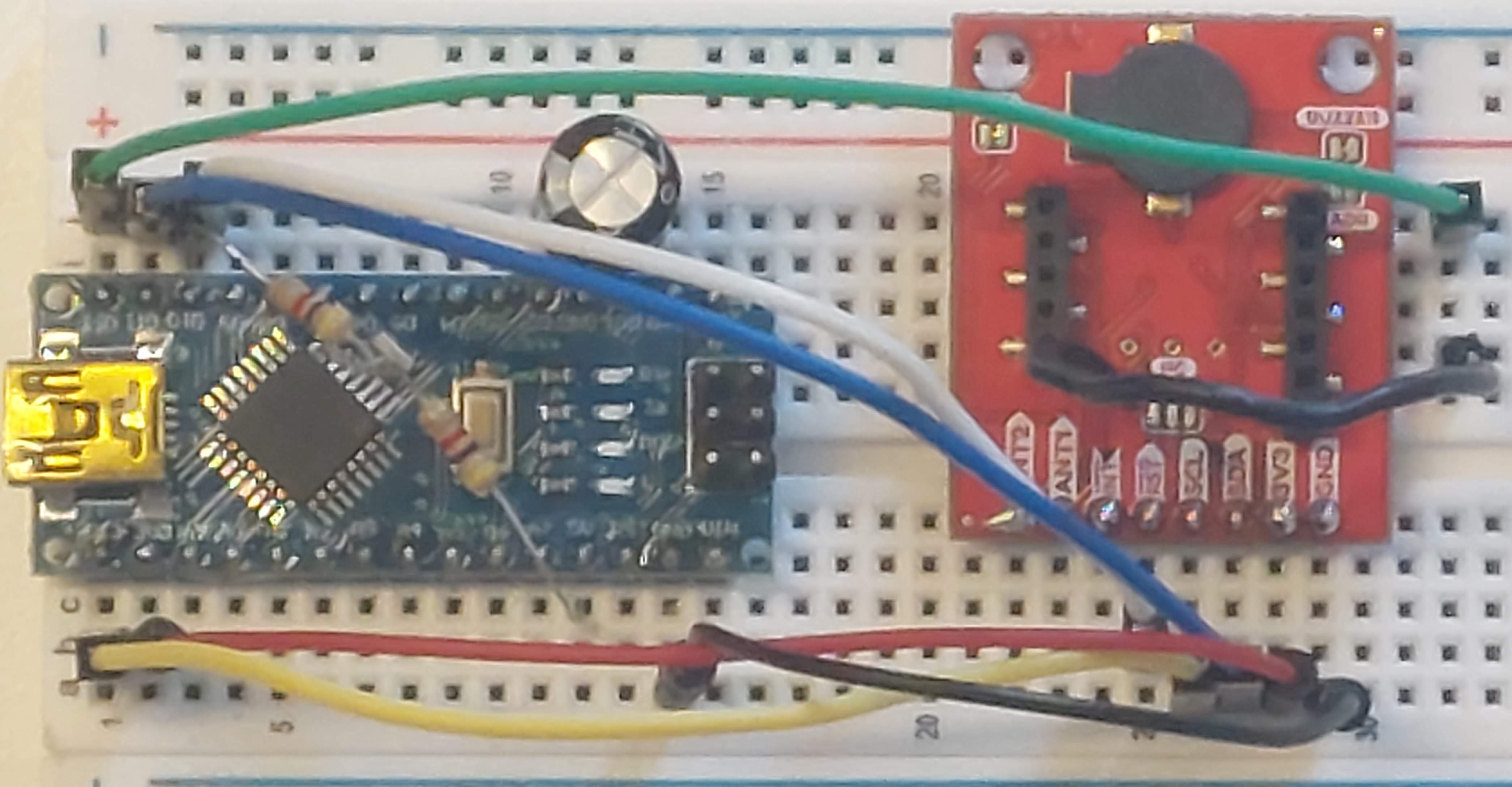
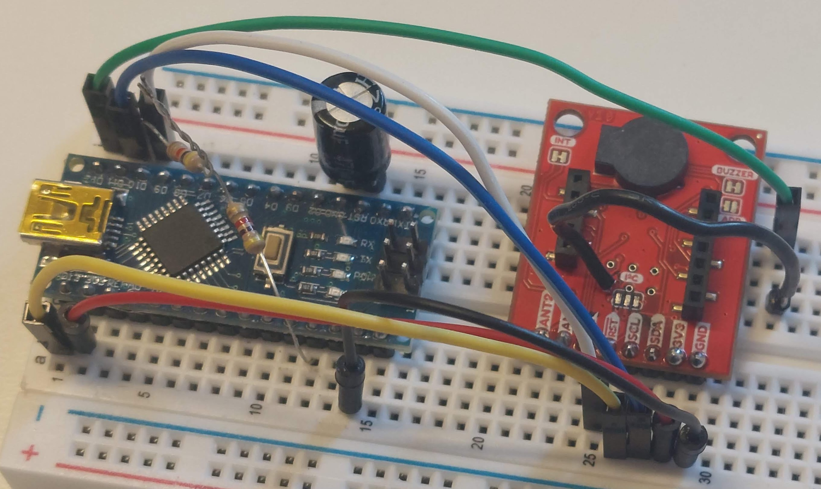
For Arduino Nano, you need to:
nfc reader => mega ; nano
3v3 => 3v3
gnd => gnd
mini pin/miso => mega (cipo/50) ; nano (cipo/d12)
sda/mosi (51) => mega (copi/51) ; nano (copi/d11)
scl => mega (sck/52) ; nano (sck/d13)
rst => mega (ss/d10) ; nano (ss/d10)
happy_kass writes that on the Qwiic board, the mini pin is the “MOSI” pin, but it is the MISO pin.
With “mini pin/miso” I refer to the little special pin left below the “I2C” label. I soldered a tiny cable there.
In addition to a capacitor (I used a 470uF, minus/stripe goes to GND) I have added a 10kOhm resistor between 5V and D10 as described in the posting here ( Arduino Nano ISP Dongle : 5 Steps - Instructables )