A dedicated and clutter-free post on this topic (originally mentioned in this one viewtopic.php?f=165&t=50580 )
Essentially, FTDI programming works fine, but you need to remove/disable the CH340 or other USB chips connected to the RX, TX and RESET signals. If it’s the first time programming, another red herring is needing to update the bootloader (either by USB or FTDI).
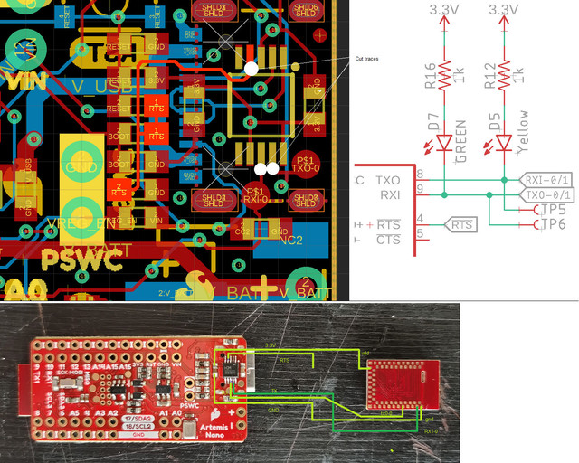
Using a custom board, which had jumpers on the TX/RX/RESET lines to prevent interference from the CH340 USB chip, FTDI programming was as expected.
FTDI success was also had using an Artemis Nano, with the FTDI wires soldered to (not in order):
3.3V pad
Gnd pad
-ve side of D7/TX LED (not to be confused with TX1 pad)
-ve side of D5/RX LED (not to be confused with RX1 pad)
_RTS node (common connection of C20/C21)
The CH340 chip was removed with a hot air desoldering gun. Make sure TX/RX cross, etc. A bit fiddly, really just for proof of concept. For custom boards, nice to have the option of omitting the CH340 chip and USB connector.
NOTE: if the FTDI connections are made and the CH340 USB chip remains connected, the error message when trying to upload by FTDI is:
Artemis SVL Bootloader
COM3 is currently open. Please close any other terminal programs that may be using COM3 and try again.
If a Serial Monitor is opened on the FTDI port, it can listen to the Artemis, and will display serial output from the Artemis. But it can’t send.
Hi,
I have bought an Artemis nano and some Artemis modules.
I would like to use the Artemis modules standalone (since they already incorporate all the needed components to work, expcept maybe voltage converter?)
I would like to upload sketches in Arduino IDE to the artemis module, using the Artemis nano as ISP programmer.
Since you were able to do this, can you please clarify a little bit?
Artemis nano 3.3V pad ↔ Artemis module 3.3V pad
Artemis nano Gnd pad ↔ Artemis module Gnd pad
Artemis nano … D7? Or TX0 (the small round dot)? ↔ Artemis module ??? (which pin)
Artemis nano … D5? Or RX1-0? (I cannot find RX0) ↔ Artemis module ??? (which pin)
Artemis nano ??? Pin (I cannot find a pin called _RTS node, nor pins calles C20/C21, just CC1 and CC2 and they are not the same) ↔ Artemis module ??? Pin
Many thanks
https://cdn.sparkfun.com/assets/5/5/1/6 … s-Nano.pdf
D7 is the name of the TX LED diode (diode 7), the electrical connection is not exposed on a PTH pin on the Nano but it goes to pad 48 of the Artemis module
D5 is the RX LED diode, the electrical connection is to pad 49 of the Artemis module
RTS is another electrical connection that does not appear on any broken-out pins. The previous description is saying that it can be identified as the trace that connects C20 and C21 (those are the names of two capacitors - capacitor 20 and capacitor 21). You can find which trace connects the two and solder to one of the capacitors to tap into that signal.
You will need to disconnect the TX/RX/RTS lines from the onboard USB->Serial converter chip as well.
Hi,
thanks for your help.
Looking at the Eagle file of the Artemis nano, (see picture) D7 is also pin TX0, available as a small round pad; and D5 is also pin Rx1. I understand where they go on the Artemis module (see picture).
I do not understand where on the Artemis module will go the RTS signal from the Artemis nano.
Also another question is: If I remove the CH340 from the Artemis nano, how can I use the Artemis Nano to upload firmware to the Artemis module, since I can’t connect the Artemis nano to USB cable to PC anymore?
Many thanks, again.
[ ](artemis1 hosted at ImgBB — ImgBB)
This post is talking about using an FTDI USB->Serial converter instead of the onboard CH340E. So the assumption is that you would no longer use the Artemis Nano as intended, but rather as a convenient way to reach the proper pads on the Artemis module.
The RTS pin does not go directly onto the Artemis module - instead it feeds an RC circuit that is in turn connected to the BOOT pin on the Artemis module. The RC circuit turns the typical RTS signals provided by USB->Serial chips into the proper signal to put the Apollo3 into UART bootloader mode
Hi,
thanks for the help.
I think I need a clarification: is this thread about using a FTDI Usb to serial converter to uplad firmware (compiled sketch from Arduino IDE) on the Artemis module that IS soldered on the Artemis nano?
Because if so, I do not see the benefit of doing it instead of using the board as is.
What I am looking is a way to upload code on a standalone Artemis module (for which I am designing a new board).
I thought that the Artemis nano was used as a programmer for the Artemis (standalone) module , the same way as you can use an Arduino Uno to program another arduino-based board using it as ISP programmer.
If I am correct (now) , at this point maybe designing a simple board where I solder the artemis module, with the jtag pins easily reachable, and using a Jtag cable, seems an easier solution?
Again, thanks for all the help.
I think this started as a thread about using an FTDI on a custom board, and stephenf also mentioned that it was possible to prove the function by replacing the CH340E on the Nano. The benefit is the ability to prove your idea before you order a custom board.
Using the Nano as a programmer for another module would be difficult because you would want to remove the built-in module and try to temporarily connect another module - which would likely not work well.
The JTAG/SWD option is very reliable and allows you to do much more than the UART bootloader alone, so I would highly recommend including the 10-pin (2x5) connector. You should also have an embedded debugger such as a SEGGER J-Link.
You can go with the UART bootloader only route - but you won’t be able to change the built-in bootloader’s settings or do single-step debugging.