The receiver can be used to provide an accurate measurement of the time at which a pulse was
detected on the external interrupt pin. The reference time can be chosen by setting the time
source parameter to UTC, GPS, GLONASS, BeiDou, Galileo or local time in the UBX-CFG-TP5
configuration message. The UTC standard can be set in the UBX-CFG-NAV5 configuration
message. The delay figures defined with UBX-CFG-TP5 are also applied to the results output in the
UBX-TIM-TM2 message.
A UBX-TIM-TM2 message is output at the next epoch if
• the UBX-TIM-TM2 message is enabled
• a rising or falling edge was triggered since last epoch on one of the EXTINT channels
The UBX-TIM-TM2 messages include time of the last timemark, new rising/falling edge indicator,
time source, validity, number of marks and a quantization error. The timemark is triggered
continuously.
That seems pretty straightforward. The example in the Sparkfun uBlox Arduino library seems pretty straight forward too. However, I have been completely unable to entice the module on my test bench to emit a UBX-TIM-TM2. I have the PPS output looped back to EXTINT, as described in the library example, and time pulse output set for once per second (default), again, as documented in the example. The Sparkfun library example doesn’t generate one. My own code doesn’t generate one. Even going into u-center and confirming configurations, and monitoring messages, doesn’t generate one.
This is all with a valid, 3D GPS position lock. This makes me think that either a) I’m missing something so obvious that it isn’t explicitly called out in any documentation or code, or b) the NEO-8MU doesn’t exactly support time mark functionality despite all documentation making it look like it does.
Please, oh wise ones of Sparkfun and community, guide me to enlightenment. What am I missing?
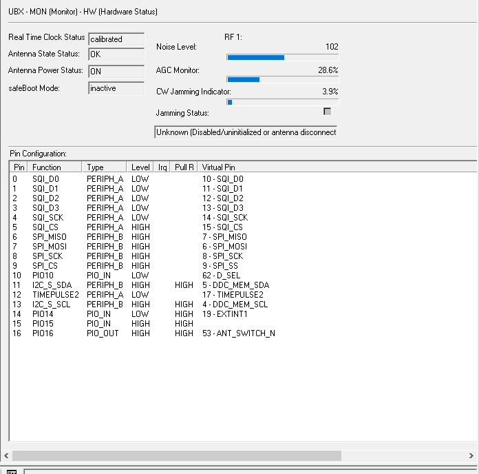
I found the same note in the Integration Guide. I spent some time in u-center playing with the different power management EXTINT pin assignments, on the theory that maybe the pin was assigned to power management functionality and that was blocking the time pulse capability. This is the pin mapping.
No amount of playing with settings seems to make a difference and, as far as I can tell, the pin mappings are read only. I did confirm that tying the INT pin high or low is reflected in the HW status message, so the pin works at that level.
Been awhile, might need to go dig up an EVK
Pin mappings are determined by what interfaces you have enabled.
How are you enabling UBX-TIM-TM2, via UBX-CFG-MSG on SPI ?
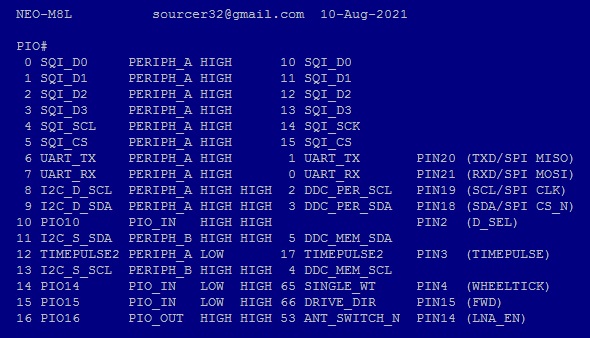
It’s on EXTINT1, not EXTINT0, and TIMEPULSE is on TIMEPULSE2/SAFEBOOT from the IC, but I think wired to the normal pin on the NEO. The Sensor (IMU) has it’s I2C on TIMEPULSE1/EXTINT0, but I think that’s masked by the firmware.
I’d anticipate that it can use a TIMEMARK/EVENTIN, although these might associate with WHEELTICK/DIRECTION PIO, the NEO-M8L data really doesn’t talk about TIMEMARK
Can you use TIMEPULSE to establish a time line in your own MCU? Perhaps via a TIM or EXTI, and then relate THAT to the thing you want to Time Stamp?
Is this for Photogrammetry or Ground Control Markers?
I’ve also confirmed it enabled, via u-center, and tried enabling it over USB in u-center. I can enable it, but never receive it.
The M8L doesn’t do TIMEMARK as the extin pin is assigned to wheel pulse instead.
Can you use TIMEPULSE to establish a time line in your own MCU? Perhaps via a TIM or EXTI, and then relate THAT to the thing you want to Time Stamp? Is this for Photogrammetry or Ground Control Markers?
Neither actually. I have a microcontroller with an external counter fed by the PPS signal at higher (10kHz) rates. An external event starts the counter on the micro and triggers the extint pin on the GPS. This gives an absolute time mark for the zero count of the counter.
I can use the PPS+TOS sync to mark the time and back calculate from that and it will likely be just fine. The system crystal for the microcontroller is good enough for a free running timer to match GPS time to 100us. However, it was nice and simple to just let the GPS give me good clean start and end marks with a GPS disciplined timing tick to drive software calculations. Now it’s just become something of a “mission” to figure out why it is the way it is.
The application, BTW, is a race computer for time over distance road racing. The wheel tick input on the M8L is useful for such an application, but requires connection to the car – and finding an M8L dev board is harder. Sparkfun had the M8U readily available for a decent enough price and the IMU capabilities give it enough accuracy so it was where I started.
The M8L and M8U share a common PCB / BoM, just a different firmware load and options.
The M8L was a part more targeted at automotive OEM customers, with much of the details under NDA.
On something like an STM32 with a 32-bit TIM it’s possible to free-run a maximal count, and then stamp/latch events on different timer channels.
Details on TIMEMARK/EXTINT1 are scant in the M8U docs. The UBX-MON-HW is definitely promising as it shows associativity of the pin to the function. I’ll have to see if I can find an EVK and loop the TP/TM pins.
"I can confirm that the TIM-TM2 function is not available on the M8U as it is running our UDR firmware.
If you aren’t using the IMU function of the NEO-M8U, you should be able to reprogram the NEO-M8U with our standard precision GNSS firmware 3.0x from NEO-M8N."
However, I’m actually pretty pleased to have a definitive answer, even if its not the one I wanted. Plus, it sounds like I have options to play with the M8N firmware and see how that works and I can weigh the capabilities of the M8U vs M8N for my application.