Do I need to hire a PCB designer for this?

I don’t have any PCB design skills, but I am a mechanical engineer and software developer so I can understand some of the basics.

I need a PIR sensor circuit that will turn a computer ON when the sensor activates, and turn it OFF when motion is no longer detected.

The MoBo I am working with is this one: http://www.intel.com/products/desktop/m … erview.htm

The PIR I am thinking of using is: http://www.sparkfun.com/products/8630, but there is also this one already incorporated into a circuit: http://www.sparkfun.com/products/9587

I am thinking the PIR would plug into the MoBo’s Power and Reset pins, and handle the Start and Shutdown.

The PIR product 8630 would be beyond my skills to incorporate, but how about product 9587? Is this something that someone that can solder, use a Voltmeter and knows how to write software could hook up and get working, or do I need to hire someone? Where to hire?

Thanks,

–Bob

why dont you do it a simpler way and put pc to ‘sleep’ the wake on lan type command

reading between lines you want to use this for some security purpose.

be mindful of the boot time AND getting it to fire the prog you want it to.

I may be totally wrong here though. just a thought

Allenf:
why dont you do it a simpler way and put pc to ‘sleep’ the wake on lan type command

reading between lines you want to use this for some security purpose.

be mindful of the boot time AND getting it to fire the prog you want it to.

I may be totally wrong here though. just a thought

The sleep mode idea would probably work. I’d still need to figure out how to wire the PIR into the MoBo so that it can wake when motion happens. Maybe the PIR can wire directly to the MoBo’s reset pins?

Thanks,

–Bob

I can’t believe no one helped you with this yet.

You most certainly do not need a PCB for this, and especially don’t need to hire anyone for this, as this is relatively simple :stuck_out_tongue:

The PIR sensor needs a supply between 5v and 12v supply, as indicated in the datasheet of the link from sparkfun. You can get the 12v supply from any of the fan connectors on the motherboard by finding a fan you do not need, and cut the wires so you have the connector to the motherboard and the wires. The red wire is 12v and the black wire is gnd. You can also use any of the power connectors from the power supply for the computer. From an ATX power supply: Black is ground, red is 5v, and yellow is 12v.

You can buy those cheap perf boards from sparkfun or radioshack instead of having to make a PCB which saves you time and cost at the expense of having it look professional.

http://www.sparkfun.com/products/8814 ← perf board from sparkfun.

Now, the problem is with the reset pin.

From the datasheet

2.2.2.4.2 Reset Switch Header

Pins 5 and 7 can be connected to a momentary single pole, single throw (SPST) type

switch that is normally open. When the switch is closed, the board resets and runs the

POST.

So you have to get the PIR sensor to connect those two pins together when it senses something to reset the computer. Reset will not turn the computer on I believe, it will only reset it if it is already turned on. What you can use instead is the power pins on the header.

2.2.2.4.4 Power Switch Header

Pins 6 and 8 can be connected to a front panel momentary-contact power switch. The

switch must pull the SW_ON# pin to ground for at least 50 ms to signal the power

supply circuitry to switch on or off. (The time requirement is due to internal debounce

circuitry on the board.) At least two seconds must pass before the power supply

circuitry will recognize another on/off signal.

The 50ms part might be a problem, but as always sparkfun does not provide much information in its datasheets. Grab a scope or something that shows you how long the alarm pin is triggered for when it senses something.

From sparkfun

If anything moves after that period, the ‘alarm’ pin will go low.

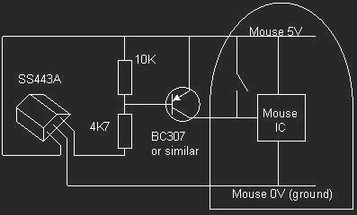
The alarm pin is an open collector meaning you will need a pull up resistor on the alarm pin.

Basically, the alarm pin is constantly pulled up to what ever voltage the resistor is connecting the alarm to. I suggest you attach the resistor from alarm to a 5v supply instead of 12v. When it senses movement, the alarm pin will go to 0v (Ground). To connect the two pins on the motherboard to power on the computer when the alarm pin goes low, I suggest you use either a mosfet, relay, or transistor.

Unfortunately I do not have enough time to continue this answer, but I am sure that if you ask for some more help on sparkfun chat, they will help you out some more.

I have seen things wired to a mouse button before. In the sleep mode this would wake up the mother board.

This is a picture of just such a thing.

http://www.cine2digits.co.uk/HEcct1.jpg

Here is a link to the page that talks about it the site uses frames so you will have to click on "Technical " in the side menu bar. It is just about half way down the Technical page.

http://www.cine2digits.co.uk/

hak8or:
I can’t believe no one helped you with this yet.

You most certainly do not need a PCB for this, and especially don’t need to hire anyone for this, as this is relatively simple :stuck_out_tongue:

Thanks hak8or! I kinda of gave up on a response, but got on the forum to read some of the latest stuff and saw your reply.

I will try what you have said and will report back my success. It’ll be a couple weeks because I am working on getting the analog video camera to work with the MB now.

–Bob

nitchvideo:
I have seen things wired to a mouse button before. In the sleep mode this would wake up the mother board.

This is a picture of just such a thing.

http://www.cine2digits.co.uk/HEcct1.jpg

Here is a link to the page that talks about it the site uses frames so you will have to click on "Technical " in the side menu bar. It is just about half way down the Technical page.

http://www.cine2digits.co.uk/

Thanks for the circuit idea, I may incorporate this into my system. I have adopted AllenF’s idea of having the PC go into “sleep” mode - this works great with the Linux system I am building - instead of power off/on. It was taking 70 secs between power cycles, so that’s no good. Sleep/wake is the way to go. So, I’ll look at using your circuit and hak8or’s ideas to see if I can get this to work.

I will report back in case others can benefit from this.

–Bob