Hi, I’m looking to build a GNSS logger for a vehicle so I can overlay telemetry data to video. Could anyone help suggest a GNSS unit? I was looking at using something with 1.5-2m accuracy, 10Hz and possibly L1/L2 (may stick with L1 to keep costs down). Thinking of paring it with an Artemis unit with built in IMU, could this help adjust the positioning when going through tunnels? I know some GNSS units have dead reckoning but if the Artemis helps supplement this option then I could use a cheaper unit.
Looking at the NEO-F10N as a possible solution. Would there be much programming involved as I’ve heard the Artemis may already be optimised for some boards? Thanks for your help.
Thanks for the recommendation. The F9R would be the top tier choice but we’ll put my budget for now. I just placed an order yesterday for:
OpenLog Artemis with IMU
NEO-F10N with SMA
Ground plate
ANN-MB5 Antenna
OLED SSD1309 display
I’m just going through doing a wiring diagram so will aim to post that for any comments to make sure I don’t mess anything up. Do you know how much work might be involved in getting the display to work with the Artemis? This is my first project so bit of a learning curve.
The standard OpenLog Artemis is preconfigured with firmware to log readings from a variety of sensors, including u-blox GNSS via Qwiic / I2C. It can also log serial data from the RX pin. But the firmware has no built-in support for an OLED. To add the OLED, you would need to modify, compile and upload the firmware.
We do have a special build of the firmware which is dedicated to logging data from u-blox GNSS modules. But that firmware expects the GNSS to be connected via Qwiic I2C, not serial. Again, there is no built-in support for an OLED. Also, that firmware is not able to log the IMU data, only the GNSS data.
In both cases, you would need to add an OLED library to support the OLED. You can use the library examples as your starting point. Please make sure that the library matches your display. Most SparkFun OLED displays are based on the SSD1306. You would need a different library for the SSD1309.
So to make life a little easier, would it be recommended to grab a multiport qwiic board and connect everything through that and avoid the serial altogether? Then your firmware build should work straight away. I’d have to look at modifying it though if I want it to log the IMU data from the Artemis?
Thanks for the link. The “The registers match that of the SSD1306 (0.96” SSD1306 Datasheet)" comment is very encouraging. You may be able to use our Qwiic OLED library as-is; our 1.3" OLED is also 128x64.
I2C is a bus. You can have multiple peripherals sharing the same bus, so long as they have unique I2C addresses. It is usual to see multiple Qwiic sensors (of different types, with different addresses) daisy-chained on a single bus.
Ah. I missed this earlier. The NEO-F10N is a special low-cost GNSS. It only has one serial UART port. Most u-blox GNSS modules have dual UART plus I2C. Sadly, that one doesn’t… So that limits your options quite a bit. You can use the standard OLA firmware to log the serial GNSS NMEA messages on the RX pin, while also logging IMU data to a separate log file. You can pull the two data sets together afterwards using the timestamps in both files.
Good luck with the project - let us know if you need more suggestions,
Paul
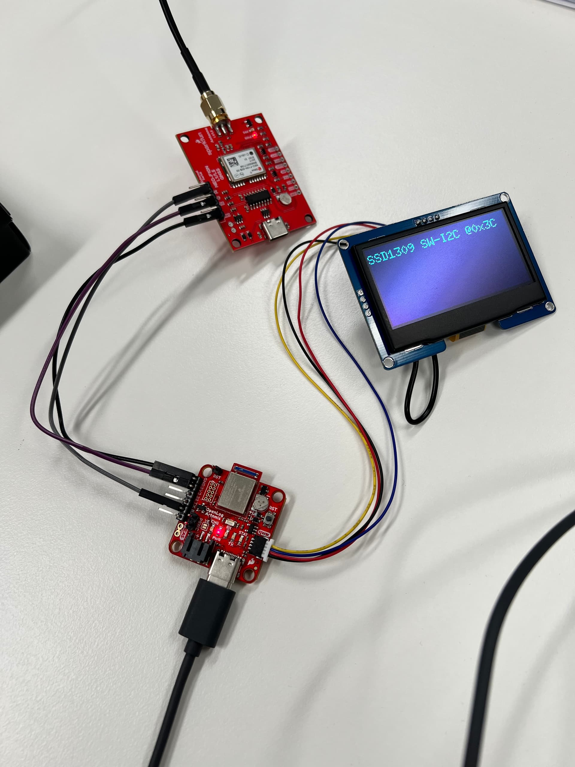
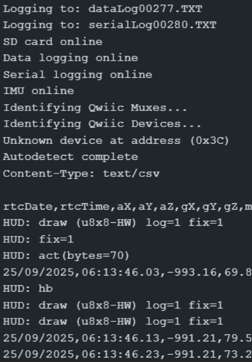
It’s taken a while to get here but I now have the OLA syncing it’s time from the F10N and both the dataLog and serialLog are timestamping. The serialLog is collecting NMEA data from the F10N. I’ve also been able to start up the OLED.
Now the current issue I’m having trouble with is displaying data on the OLED. I’ve been trying to get it to change between IDLE and LOG once it starts recording serial data and getting it to change between FIX and NO FIX once it’s got enough satellites. Do you know if this is possible? Heads up, all the coding has been done by ChatGPT, it’s been a bit learning curve for me and I’ve realised it’s no where near perfect and I need to take baby steps with the code, but it’s got me this far. It just hasn’t been able to display this data yet with more planned. I used the latest firmware as the base and went from there.
Thanks for sharing those links, I had a read through them and guided chatGPT to the examples page. I’m still having trouble with it flipping the states on the OLED. It did some testing and looks like it can see when the log is writing and when it has a fix, but ChatGPT doesn’t seem to know how to have the status on the OLED toggle from say ‘Idle’ to ‘Log’ and from ‘No Fix’ to ‘Fix’. This has been the hardest part of the project so far and I’ve spent a fair bit of time back and forth. Do you have any samples or can guide me to a page that I can use to point chatGPT in the right direction for toggling the status? I did have it try the SparkFun library for the OLED to see if that helped, but then it couldn’t get the screen to fire up at all.
I think you’re being overly optimistic, expecting AI to write such application-specific code for you with little direction. Why not give the examples a try yourself? Make your changes one at a time and re-test. You’ll soon figure out what works and what doesn’t…
If AI is your only choice, then a coding-specific AI like GitHub Copilot may provide better results.
Don’t forget to enable the power for the Qwiic interface. The I2C_Detector test sketch may be a good place to start. Look for the references to PIN_QWIIC_POWER.
After a few months break I got back into trying to get the OLED to work. Originally I was using ChatGPT 5.0 and it’s now on 5.2 so thought I’d give it a crack. No luck, just kept making things worse so movies over to GitHub Copilot. If I had started with GitHub, the whole project would have been done quicker. Worked a lot better in the end than ChatGPT. Took a few tweaks but eventually got it to display everything I want along with recording serial and IMU data at 10Hz. Now to see if I can overlay the telemetry data on a video recording.
I’m sure the code isn’t as clean or efficient as it can be, but for someone with no coding experience, I’m pretty happy with it and I’ve learnt a few things along the way.
Hi Paul,
Am I able to upload the files here? I can’t see any methods that’ll let me upload the .zip folder.
I ended up using your GNSS code as a base to simplify the overall setup and remove all the additional sensor data. I had issues with the old code and the GNSS logs being partially corrupted. This new code has helped a bit but only has about 83% of the data I can use, may be a buffering issue. Hopefully I can get that fixed, then I think I’ll have it where I want it. If I can’t upload the files here, what’s the best way to share them?
GitHub or GitLab would be good choices for sharing your code. Or, you can upload it here by renaming it and adding “.pdf” on the end of the filename (my_code.zip.pdf).
Just a heads up, this one was all done by Github, going back and forth working on one item at a time. First I got the GNSS logging NMEA data via serial, then the IMU logging, next I had the OLE sync it’s time to my F10N and lastly enabled the OLED. It’s logging RMC and GGA both at 10Hz and IMU data at 10Hz.