Hi, I have a challenge and hope someone has and idea how to solve it.
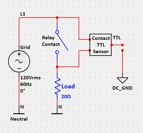
I want to monitor the health of a relay by monitoring the state of relay contacts in relation with the state of the coil. I want to see if the contacts are open or closed when the coil is energized or not energized. I want to do this with an Arduino. It must be something like you see in the drawing below.
Can you tell me if there is a component or sensor that can do this. Let me know what idea you have how this can be done.
If I understand correctly, you want to measure the small AC voltage that is generated across failing relay contacts? If the relay contacts are perfect: when open, your sensor circuit gets very close to the full 120VAC; when closed, your sensor circuit gets zero volts AC (but is still at hazardous Live Line voltage, compared to Earth). When the contact is failing, you will see a small AC voltage across the closed contacts because the contacts have some resistance.
To do it safely, I’d recommend using two safe, opto-isolated AC multimeters: one measuring L1 to N; the second measuring the Load voltage to N. Subtract one from the other and you have the voltage drop across the contacts.
Or, keep it simple and use a single opto-isolated multimeter that can auto-range safely from the full 120VAC to the small AC voltage across the closed contacts.
There are low cost multimeters available which have an opto-isolated USB interface. I have a “BOLYFA 117” meter with a mini-USB interface. I wrote some Python 2 code to read the interface. (Side note: the interface is weird in that you read data representing what is displayed on the LCD display segments - i.e. if each segment is on or off. You have to convert each 7-segment digit into a number.) You could re-use that code on (e.g.) Raspberry Pi or another single board computer which supports USB.
For a true “Arduino” solution, you’re probably going to want meter(s) which have opto-isolated serial (UART) interfaces. Sounds like a job for Google. (Other search engines are available…!)