Intermittent and unexpected results with a Qwiic Iridium 9603N

I am having significant issues with this device.

Sometimes it appears to work, but mostly I get unexpected errors.

I’m using the standard examples from this library

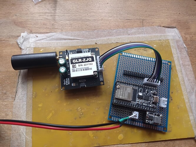
I’m using a classic ESP32 with an external 3A 5V power supply for both devices.

I haven’t paid for airtime yet, so have only tried the Get IMEI and Get Signal Quality.

I have added two 10F supercapacitors.

When I first used it, it wouldn’t get the serial number, now it seems to work sometimes, as long as I comment out the supercapacitor code. It never seems to recognize that the super capacitors are fully charged.

When I try the signal quality sketch, it only works if I set diagnostics to true, this is probably related to this issue:

But I’m not sure how to turn off the echo over the I2C interface.

This is the output from the signal strength sketch, with the super capacitor code commented out and diagnostics set to true.

12:53:42.711 → Iridium SBD Check CSQ I2C
12:53:42.711 → Press any key to start example.
12:54:00.153 → Enabling 9603N power…
12:54:00.153 → Starting modem…
12:54:00.153 → Calling internalBegin
12:54:00.153 → Powering on modem…
12:54:00.679 → >> AT

12:54:00.679 → Waiting for response OK
12:54:00.679 →
12:54:00.679 → << AT

12:54:00.679 → OK
12:54:00.679 → >> ATE1

12:54:00.679 → Waiting for response OK
12:54:00.679 →
12:54:00.679 → << ATE1

12:54:00.679 → OK
12:54:00.679 → >> AT&D0

12:54:00.679 → Waiting for response OK
12:54:00.679 →
12:54:00.679 → << AT&D0

12:54:00.679 → OK
12:54:00.727 → >> AT&K0

12:54:00.727 → Waiting for response OK
12:54:00.727 →
12:54:00.727 → << AT&K0

12:54:00.727 → OK
12:54:00.727 → Ring alerts are enabled.
12:54:00.727 → >> AT+SBDMTA=1

12:54:00.727 → Waiting for response OK
12:54:00.727 →
12:54:00.727 → << AT+SBDMTA=1

12:54:00.775 → OK
12:54:00.775 → >> AT+CGMR

12:54:00.775 → Waiting for response OK
12:54:00.775 →
12:54:00.775 → << AT+CGMR

12:54:00.871 → Call Processor Version: TA21004
n: 0x001a (GRFA1Unknown FW version
12:54:30.810 → MSSTM workaround is enforced.
12:54:30.810 → InternalBegin: success!
12:54:30.810 → >> AT+CGMR

12:54:30.810 → Waiting for response OK
12:54:30.810 →
12:54:30.810 → << AT+CGMR

12:54:30.858 → Call Processor Version: TA21004
n: 0x001a (GRFA1FirmwareVersion failed: error 3
Hi @vwvanman ,

Welcome!

Please post a photo of your setup, clearly showing the connections between the ESP32 and the Qwiic Iridium.

I’m wondering why you added the extra 10F capacitors? The standard 1F ones should work well for most applications. You only need the extra capacitors if you need to decrease the capacitor charge current to 60mA.

The extra 10F capacitors will take a long time to charge. How long are you waiting for the capacitors to charge?

Have you checked the capacitor polarity? Could one of them be installed the wrong way round?

I have not seen the GRFA1Unknown FW version and GRFA1FirmwareVersion failed: error 3 errors before. I wonder if they are caused by the capacitor voltage being too low?

You should not need to change the echo settings. The code library will set ATE1 for you.

I hope this helps,
Paul

Because they are on the schematic and silk screen

1 Like

Yes, of course I did, I double checked before soldering them

I can see the library sending the command, but it doesn’t seem to stop the echo. You can see this above.

I also tried the high (not usb) power setting.

I’ve waited about ten minutes.

I’ll desolder the super capacitors later and try again.

Hi @vwvanman ,

Thank you for the photos.

Do you have a schematic or wiring diagram you can upload?

It is difficult to tell from the photos, but it looks like you have 5V from your buck regulator connected to the 5.3V output on the Qwiic Iridium? That probably explains your difficulties.

The super-capacitors are charged by the LTC3225 super-capacitor charger. It is powered from 3.3V and boosts that up to 5.3V as it charges the capacitors. The 5.3V output is there so you can monitor the capacitor externally.

If you want to power the 9603N modem direct from your buck regulator, we can discuss that. But the Qwiic Iridium wasn’t designed with that in mind.

Best wishes,
Paul

Thanks
Yes, it is currently powered from the 5V pin.
I’ll swap to a 3.3V buck module and power the ESP32 and the Iridium module from that.
I’ll let you know how I get on.

I would like to say that it is not clear from the schematic that EXT_PWR is an output not an input. Is this noted or stated anywhere?

The Qwiic Iridium is a true SparkX speed-over-polish product. There is some documentation here which I hope will help, but even that doesn’t tell you that 5.3V is an output. It is far from complete - I’m sorry about that.

Yes, please do power the Qwiic Iridium from 3.3V. You should see big improvements once you’ve done that. You may be able to use a 3.3V output from the ESP32 board, but I don’t know how much spare capacity its regulator has. If it can provide an extra 200mA, you should be OK.

Best wishes,
Paul

1 Like

Hi Paul
Well spotted on the 5V power.
I swapped to a 3.3V 3A buck module and am now powering the ESP32 and the iridium modules via their 3.3V pins.
That was the problem, it works as expected now :slight_smile:
It even charges the 10F supercapacitors in a few seconds.
Thanks
Jem

1 Like

Hi Jem,

Thanks for the update. I’m glad you got it working.

Best wishes,
Paul