Layout a simple fence line?

@steve1428 , what you are looking for is COGO, or COordinate GeOmetry.

Most paid Data Collector Apps have COGO functions.
There may very well be freeware apps with it also.

You would establish the bearing with the 2 endpoints of a straight section, then create points @12’ along that bearing.

2 Likes

yes they do it’s called FieldGenius, it’s a lot of money
there are others.
they won’t even sell to you unless you’re a surveyor, they’v’e got a little gps exclusion club

Go to chatgpt.com and type in the following prompt:

I have two end points with known lat/long coordinates. Write a python program that prints points at 12 foot intervals on the line between the two points.

Some years ago, I built a F9P rtk base-rover pair with an arduino on the rover that calculated and displayed bearing and distance from the last reference point I had recorded.

Something like this would work nicely for the OP to lay out a series of fence posts in a straight line from an origin point.

For example, in the photo below, the rover is 92.51 feet N85.40°W from the reference point I had set.

1 Like

very nice
SW maps has the staking function that directs you to the next location,

when i have some time i’ll play with the COGO thing, I think that’s the way to create these waypoints along the fence line and just upload a kml file to sw maps

I did a very similar thing a few years ago with the Ublox C94-M8P base-rover pair.

The two-component kit is entirely self contained, with integrated radios so they communicate out of the box over many km, line of sight.

Once the base “survey-in” was complete, relative positioning accuracy was stable and as advertised (comprehensive tests and review). Setup and operating instructions were very clear.

Still a few kits left at USD 448:

i’ve spent a thousand bucks and can’t even get an autonomous base setup

Great write-up!

I just followed this tutorial Setting up a Rover Base RTK System - SparkFun Learn, and used the SF arduino libraries to pull in the data and my own amateur coding skills to pipe it onto a little OLED screen

I think the F9P itself also sent the data over USB to SWMaps, as I don’t recall coding the arduino to do that.

I highly recommend that tutorial.

i can get it to work with known coordinates plugged in.

this exercise of collecting raw data and converting it to rinex just doesn’t work with the app i’m using and i don’t think i can get at the lg290p through the usb to use qgnss app.

Ho rispolverato i libri di geometria piana…
…ricordo che qualche pigro topografo giocava con G_Earth e che in effetti dava risultati
soddisfacenti,senza far storcere il naso ai geometri ortodossi.

The technique used is to convert the WGS84 coordinates into UTM plane coordinates.
You have to pay attention to the zone you use and stay within it.Google Earth Pro can do it.
E.g. U have 34,801472°N , 114,083487°W into search_bar as placemark
then go in tools_options and
immagine
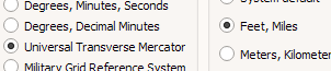
then R_click on the placemark and in properties can see UTM coordinate.


take note 766818.31 m E ; 3854905.21 m N are the plane coord. (to use in a cartesian p.in meters)
the formula to calculate the distance between two points is:
d = √((x2 - x1)² + (y2 - y1)²) where x=easting & y=northing
need the Unit_vector as ( (x2 - x1) / d, (y2 - y1) / d )
and the Displacement_vector of n meters as n( (x2 - x1) / d, (y2 - y1) / d )
so need to add the n*Unit_vector couple to the first point:
e.g. for 100m distance ,if the couple of Unit_vector is (0.69,0.71) will be
(x1 + 69,y1 + 71) if the bearing y=Northing go to north…(as in A)

let say second point has 766947.00 m E ; 3850370.00 m N
need distance:

d=766947.00-766818.31= (128.69)²=16561.1161
3850370.00-3854905.21=(-4535.21)²=20568129.7441
16561.1161+20568129.7441=√20584690.8602=4537.03547046m

now Unit_vector:
U_v_x=766947.00-766818.31=(128.69)/4537.03547046=0.02836433632
U_v_y=3850370.00-3854905.21=(-4535.21)/4537.03547046=-0.99959765127
U_v=[|0.02836433632 , 0.99959765127|] ( | mean absolute value)
if U see the


second point (B) has x positive and y negative and the vector_direction coordinate are (x,-y)
instead if the second point is in C it has (-x,-y) and so on
So,take a point at 150m…
150 (0.02836433632 , 0.99959765127) → |( ±4.254650448 , ±149.939647691)|
so
766818.31+4.254650448=766822.56465 for x
3854905.21 - 149.939647691=3854755.27035 for y
P150m has 766822.56465 m E ; 3854755.27035 m N
that in WGS84 is


now U can mark points and convert into kml or gpx…for other apps.
A programmer would be needed for the auto-calculations.

1 Like

I spent $400 for my C94-M8P kit and was up and running in less than an hour, following the instructions. However, survey-in can take many hours to get a decent base location.

BTW it comes with a pair of active antennas with handy ground planes.

i’m exaggerating, two good antennas were couple hun, and the boards were around 200 each, cables, etc, shipping, it adds up

yes i saw that on a land survey the other day, “NAD83”
I’m trying to learn this.
but the property line itself seems to be the same long and lat as indicated on the county GIS maps.
I think the GIS is in the same system as the GPS receiver.

Maybe I shouldn’t have told you about NAD83(2011), because maybe you won’t use it at all. I don’t know how you will plot the measurement results in your CAD application. If you use a public base station in RTK, the result will be in NAD83(2011).

  1. If you perform a measurement without a base station, the measurement result will be in WGS84.

  2. If you are measuring with a base station, the result will be in the system in which you entered the base station coordinates (because the rover’s position is determined relative to the base station):

    a) if you are measuring with your own base station in Fix position mode and you enter its coordinates in WGS84, the result will be in WGS84,

    b) if you are measuring with your own base station in Survey-in mode, the result will be in unknown system based on shape WGS84, because WGS84 is assumed by default,

    c) if you are measuring with a public base station and its coordinates are given in NAD83(2011), the result will be in NAD83(2011),

    d) if you are measuring with your own base station in Fix position mode and you enter its coordinates in NAD83(2011), the result will be in NAD83(2011),

Explanation: WGS84 is the Earth’s coordinate system. Individual countries have adopted their own coordinate systems so that measurements can be made relative to their permanent base stations. The US currently has the NAD83(2011) system. NAD83(2011) is based on the same shape of the globe as WGS84, but has an offset from WGS84.

GPS measurements are made in 3D systems such as WGS84 and NAD83(2011).

The measurement results are transformed to a 2D system with an additional height so that they can be presented to scale on a flat surface such as a map. Such a transformation is called a projection. There is a whole catalog of projections. Examples of projections:

a) for Google and OpenStreetMap maps
   WGS84 -> EPSG:3857

b) for maps with plots
   NAD83(2011) -> State Plane Coordinate System (SPCS)- NAD83/Arisona Central(ft)

I don’t know what coordinate system your county GIS maps are in. If it’s an aerial photo, it’s probably just an approximation.

the surveys state they are in NAD83 so all I have to do is put my base on top of a marker close by and then find an RTK fix position on my land where I want to put my base station.

OK. This method can also be used. If the marker coordinates are given x[ft], y[ft] in NAD83/Arisona Central(ft) you will probably need to convert them to NAD83(2011).

If you were to set your base station with coordinates in WGS84, your station’s coordinates could change at any time because the Americas tectonic plate and the ground are shifting.

Continental drift is certainly a major concern for laying out a cow fence.

2 Likes

look man, i bought this precision gps stuff and i’m gonna use it even if it’s to layout a cow pond!

1 Like