Yes, R3 and C2 seem to have been rotated. But in the current configuration this is easier to mod. In the old configuration it was easier to accidentally unsolder the other components. Just unsolder R3 (or both for that matter as C2 useless anyway) and fill it as a solder jumper. Then UVLO never even comes close to 0.25 volt. (Well, it will when the input power goes below 0.25 volt) Or replace it with a different value resistor based on the formulas in the datasheet.
Like in the older model, the light brown component is the capacitor (C2). The black one is the resistor R3. The one nearest the negative terminal of the JST connector. However, I can’t make heads or tails out of why they used those ‘30E’ resistors on the product image: https://cdn.sparkfun.com//assets/parts/ … 55-03a.jpg
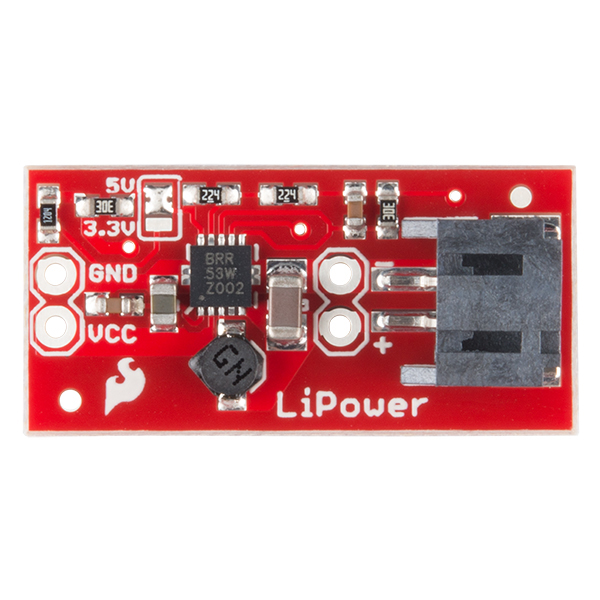
[Edit: Solved it, according to this table 30E is indeed a 2 Mega ohm resistor. EIA-96 number coding is weird! https://www.hobby-hour.com/electronics/ … istors.php]