Hello all!
I bought a Pro-Micro 5V and it works fine. I’ve tried a few different sketches and even connected output to a processing sketch. I got curious about an arduino oscilloscope to look at signals and found a project that uses an UNO while I have a Pro Micro/Leonardo. Here’s the link to the project I refer: https://www.instructables.com/Oscillosc … rocessing/
In that link is a link to the arduino code. I’ve looked at it and the first example uses four pins; ~10,A0, ~9,A1
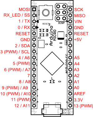
~10 connected to A0 and ~9 connected to A1 is marked on an UNO. When I look at the Sparkfun hookup guide for the Pro-Micro file:///media/fuse/crostini_d114572d6563ee5f9eb2c06fe3a3c1dec2d5fd6a_termina_penguin/Arduino/ProMicro&Fio_v3_HookupGuide_Web.pdf on page 3, I see it also has A0,A1,A2,A3 but then I don’t see ~10 or a ~9.
I tried just hooking up 10 to A0 and 9 to A1 on the Pro Micro but the BegOscopio V1.3 doesn’t see the output. I can connect serial which is good, but no oscilloscope output.
Here’s the direct links to the arduino code and processing code:
Arduino code: https://github.com/rogeriobego/oscillos … rduino.zip
Processing code: https://github.com/rogeriobego/oscillos … source.zip
How do I translate/convert ~10 and ~9 to pins on the Pro Micro?
Oh, here’s code snippet(lines 88 thru 135) that shows some pins:
//--------------- Ler Resistor/Capacitor ---------
boolean lerRC=false;
#define pinV 5
#define pinA 7 // pino A 10 multiplex
#define pinB 8 // pino B 9 multiplex
byte entrada=0;
int vi, vf, v;
//float rx=0, cx=0;
//float r[]={0.0,200.0,20000.0,1000000.0};
//float re[]={0.0,145.2,20692.9,1017847.5};
//float vcc[]={0,871.5,1026.3,1027.1};
unsigned long dtRC=0;
char unidadeRC=' ';
boolean debug=true;

void setup() {

 //---------- configura o preescaler do ADC ======
 ADCSRA &= ~PS_128;  //limpa configuração da biblioteca do arduino

 // valores possiveis de prescaler só deixar a linha com prescaler desejado
 // PS_16, PS_32, PS_64 or PS_128
 //ADCSRA |= PS_128; // 64 prescaler
 //   ADCSRA |= PS_64; // 64 prescaler
 //  ADCSRA |= PS_32; // 32 prescaler
  ADCSRA |= PS_16; // 16 prescaler
//=================================================

  //definir Timer1 pwm(pino9) e pino10 para monitorar freq
  pinMode(10,OUTPUT);
  //vou inicializar com 10Hz (100ms=100000us)
  Timer1.initialize(pwmP); //100000us=100ms=>10Hz
  Timer1.pwm(9,map(pwmPon,0,100,0,1023)); //pwm no pino9 com 25% duty cycle
  Timer1.attachInterrupt(callback); //attaches callback() como timer overflow interrupt
  //Timer1.stop();

  //inicializar A0, A1, A2, A3 com pull_up
  // não ficou bom pois qdo não tem nada conectado na porta, ela fica
  // com 5v. O melhor é colocar um pull_down com resistor
  //  A0___|R=20k|___GND
  //     |__ Vinput
  /*
   * pinMode(A0,INPUT_PULLUP);
   * pinMode(A1,INPUT_PULLUP);
   * pinMode(A2,INPUT_PULLUP);
   * pinMode(A3,INPUT_PULLUP);
  */

