DEAR ALL.
I am using(LaunchPad MSP430G2553)
I am having totally 16 pins available I.e GPIO other than gnd/vcc/RST
i have totally 20 pin as out put.
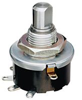
4 for speed selector like 100,200,300,400,600in rpm using potentiometer(http://in.element14.com/multicomp/mcrm4 … dp/1522038)
4 for motion control selector fw,rv,stop using potensiomete(http://in.element14.com/multicomp/mcrm4 … dp/1522038)
2 for motor drive
2 for analog sensor
2 RTC pin(ds1307)
2 for GPS
4 for operation selector-> init ,manual, automatic,use defined.(http://in.element14.com/multicomp/mcrm4 … dp/1522038)
Is there any way to reduce pins for connection. I never want to go with resistor selector network. If any other method, please share me link
is there any way i can reduce my pin configuration using external circuit.
like MUX where i can give multiple input from selector and out put can read in analog format.