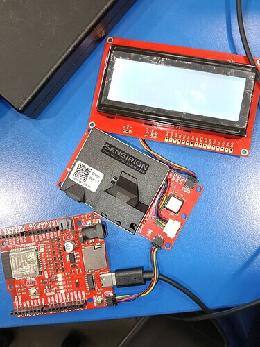
what does the error message mean? does that mean i have issue connecting the board to the port?
// ==== Blynk Configuration ====
#define BLYNK_TEMPLATE_ID "Type template ID
#define BLYNK_TEMPLATE_NAME “Type template name”
#define BLYNK_AUTH_TOKEN “Type Auth Token”
#include <BlynkSimpleEsp32.h> // Make sure this library is installed
char ssid = “Type wifi name”;
char pass = “type wifi password”;
// ==== I2C and Sensor Libraries ====
#include <Wire.h>
#include <SensirionCore.h>
#include <SensirionI2CSen5x.h>
#include “SparkFun_SCD4x_Arduino_Library.h”
#include <SerLCD.h>
// ==== Sensor and Display Instances ====
SensirionI2CSen5x sen5x;
SCD4x scd4x;
SerLCD lcd; // Default I2C address 0x72
// ==== Measurement Variables ====
float pm1p0, pm2p5, pm4p0, pm10p0;
float sen5xHumidity, ambientTemperature, vocIndex, noxIndex;
void setup() {
Serial.begin(115200);
delay(250);
Wire.begin();
// ==== Initialize Blynk ====
Blynk.begin(BLYNK_AUTH_TOKEN, ssid, pass);
// ==== Initialize LCD ====
lcd.begin(Wire);
lcd.setBacklight(255, 255, 255);
lcd.setContrast(5);
lcd.clear();
lcd.print(“Initializing…”);
// ==== Initialize SEN55 ====
sen5x.begin(Wire);
uint16_t error;
char errorMessage[256];
error = sen5x.deviceReset();
if (error) {
errorToString(error, errorMessage, 256);
Serial.println("SEN55 Reset error: " + String(errorMessage));
lcd.clear(); lcd.print(“SEN55 Reset Err”);
}
float tempOffset = 0.0;
error = sen5x.setTemperatureOffsetSimple(tempOffset);
if (error) {
errorToString(error, errorMessage, 256);
Serial.println("Temp Offset Error: " + String(errorMessage));
}
error = sen5x.startMeasurement();
if (error) {
errorToString(error, errorMessage, 256);
Serial.println("SEN55 startMeasurement error: " + String(errorMessage));
}
// ==== Initialize SCD41 ====
if (!scd4x.begin()) {
Serial.println(“SCD4x not detected. Check wiring!”);
lcd.clear(); lcd.print(“SCD4x Not Found”);
while (true); // Halt
}
lcd.clear();
lcd.print(“Sensors Ready”);
delay(2000);
lcd.clear();
}
void loop() {
Blynk.run();
uint16_t error;
char errorMessage[256];
error = sen5x.readMeasuredValues(
pm1p0, pm2p5, pm4p0, pm10p0,
sen5xHumidity, ambientTemperature, vocIndex, noxIndex
);
if (!error) {
Serial.print("PM2.5: “); Serial.print(pm2p5);
Serial.print(” ug/m3, Temp: “); Serial.print(ambientTemperature);
Serial.print(” C, Hum: "); Serial.println(sen5xHumidity);
// ==== LCD Display ====
lcd.setCursor(0, 0);
lcd.print("PM2.5:"); lcd.print(pm2p5, 1);
lcd.print(" T:"); lcd.print(ambientTemperature, 1);

lcd.setCursor(0, 1);
lcd.print("Sec:"); lcd.print(millis() / 1000);

// ==== Blynk Virtual Writes ====
Blynk.virtualWrite(V0, pm2p5);
Blynk.virtualWrite(V1, ambientTemperature);
Blynk.virtualWrite(V2, sen5xHumidity);
Blynk.virtualWrite(V3, vocIndex);
Blynk.virtualWrite(V4, noxIndex);
Blynk.virtualWrite(V5, pm10p0);
} else {
errorToString(error, errorMessage, 256);
Serial.println("SEN55 Read Error: " + String(errorMessage));
}
// ==== SCD41 CO2 Readings ====
if (scd4x.readMeasurement()) {
float co2 = scd4x.getCO2();
float scdTemp = scd4x.getTemperature();
float scdHum = scd4x.getHumidity();
Serial.print("CO2: "); Serial.print(co2); Serial.print(" ppm, ");
Serial.print("Temp: "); Serial.print(scdTemp); Serial.print(" C, ");
Serial.print("Hum: "); Serial.println(scdHum);

lcd.setCursor(0, 2);
lcd.print("CO2:"); lcd.print(co2);

// ==== Send to Blynk ====
Blynk.virtualWrite(V6, co2);
Blynk.virtualWrite(V7, scdTemp);
Blynk.virtualWrite(V8, scdHum);
}
delay(1000); // Read interval
}


