//#include "HardwareSerial.h"
HardwareSerial NanoSerial(2);

// these are the default of HardwareSerial2 but in case you want to change.
#define Serial_RX 16
#define Serial_TX 17
If you use this then for every change in baudrate you have to set the complete
Something very weird… in the test sketch I had added nano.enableDebugging(Serial); before if (setupNano(38400) == false) in setup(). This was to get driver-debug and check it was working. I have removed that before posting the example_ESP32.
Based on your feedback I have tried the example without nano.enableDebugging(Serial)… and it fails??? I have traced it down that the (recent updated) ESP32 needs a delay of 1ms instead of displaying the debug messages in order to work. A yield will not do the job.
For a long time I have been adding functions to the original Sparkfun library and have now created version 2.2 which has a 2ms delay included (only for ESP32). remove the original Sparkfun library and use this version : https://github.com/paulvha/ThingMagic/b … ay2021.zip
Now to your question on TX from Nano / RX for ESP32 in rest the voltage is ~0.1V.
I am starting to run out of ideas. It must be something very basic. Just some thoughts.
If you have a USB / Serial breakout (like https://www.sparkfun.com/products/15096) try to connect that a windows computer and use the Thingmagic Universal Reader Assistent(URA) to connect
Double-check the wirings.
I was wrong in my earlier measusrement. In rest nothing happening pin 16 (from the voltage divider) reads 2.3V, and pin 17 (rxd on Nano) read 3.3V), VCC on the Nano reads 4.52V
Add nano.enableDebugging(Serial); before if (setupNano(38400) == false) in setup(). see what messages you get.
There is no response on the request for the firmware and hardware level (the first command) and then is put to adjust the speed and the request is tried again and failing. This normally is a hardware setup issue.
1. Remove the external antenna for now and also the plastic cover.
Make sure the pins on the sides of the NANO are not connecting/touching to anything.
Your connection looks correct to me. You get the power (else the led would be off).
It must be connected to 5V, else it will not work.
Make sure the serial2 is selected and thus pin 16 and 17.
Power all OFF and ON again. (once the NANO is in a state of flux it needs a power cycle to restore.)
if you happen to have a USB/serial FTDI, you could try with the URA on Windows
double check that your breakwires do connect correctly. Have had situations where that was not the case[/list
11:27:14.766 → Module failed to respond. Please check wiring.
I have used a multimeter and my power is good (4.4V at the nano), and my voltage divider seems to be working (2.3V at RX2 aka pin 16 on ESP32). RX is 3.2V for what that’s worth. I am using the example1_ESP32 sketch Paul uploaded. Any ideas or success stories here?
Okay, I got it working. I used the Example1_HardwareSerial_Constant_Read sketch, and the only thing I changed was turning all instances of “Serial5” into “Serial2” instead (copied below). I did not change anything on my wiring and setup. I do not know why this worked and the example sketches posted in this thread did not. From a cursory glance, the only difference in the official example sketch and the ones here that I noticed was a 115200 serial speed instead of 38400.
/*
Reading multiple RFID tags, simultaneously!
By: Nathan Seidle @ SparkFun Electronics
Date: October 3rd, 2016
https://github.com/sparkfun/Simultaneous_RFID_Tag_Reader
KCCR May18 2022:changed Serial5 to Serial2 and used with ESP32
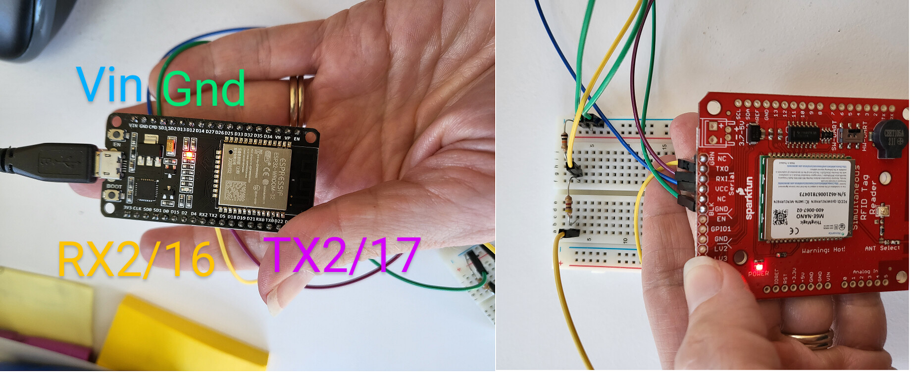
I used this example with an ESP32 (in my case the DOIT DEVKIT V1) and the hardware serial pins.
I used Serial2, which corresponds to RX2 and TX2 on pins 16 and 17 respectively.
The serial slide switch must be in the 'HW-UART' position
Connections:
Nano ESP32
GND GND
VCC VUSB
RXI 17 (make sure to have voltage divider /resistors in place to bump 5V logic on nano down to 3.3V for ESP32)
TXO 16
*/
#include "SparkFun_UHF_RFID_Reader.h" //Library for controlling the M6E Nano module
RFID nano; //Create instance
void setup()
{
Serial.begin(115200);
while (!Serial); //Wait for the serial port to come online
//Because we are using a hardware serial port in this example we can
//push the serial speed much faster to 115200bps
if (setupNano(115200) == false) //Configure nano to run at 115200bps
{
Serial.println(F("Module failed to respond. Please check wiring."));
while (1); //Freeze!
}
nano.setRegion(REGION_NORTHAMERICA); //Set to North America
nano.setReadPower(500); //5.00 dBm. Higher values may caues USB port to brown out
//Max Read TX Power is 27.00 dBm and may cause temperature-limit throttling
Serial.println(F("Press a key to begin scanning for tags."));
while (!Serial.available()); //Wait for user to send a character
Serial.read(); //Throw away the user's character
nano.startReading(); //Begin scanning for tags
}
void loop()
{
if (nano.check() == true) //Check to see if any new data has come in from module
{
byte responseType = nano.parseResponse(); //Break response into tag ID, RSSI, frequency, and timestamp
if (responseType == RESPONSE_IS_KEEPALIVE)
{
Serial.println(F("Scanning"));
}
else if (responseType == RESPONSE_IS_TAGFOUND)
{
//If we have a full record we can pull out the fun bits
int rssi = nano.getTagRSSI(); //Get the RSSI for this tag read
long freq = nano.getTagFreq(); //Get the frequency this tag was detected at
long timeStamp = nano.getTagTimestamp(); //Get the time this was read, (ms) since last keep-alive message
byte tagEPCBytes = nano.getTagEPCBytes(); //Get the number of bytes of EPC from response
Serial.print(F(" rssi["));
Serial.print(rssi);
Serial.print(F("]"));
Serial.print(F(" freq["));
Serial.print(freq);
Serial.print(F("]"));
Serial.print(F(" time["));
Serial.print(timeStamp);
Serial.print(F("]"));
//Print EPC bytes, this is a subsection of bytes from the response/msg array
Serial.print(F(" epc["));
for (byte x = 0 ; x < tagEPCBytes ; x++)
{
if (nano.msg[31 + x] < 0x10) Serial.print(F("0")); //Pretty print
Serial.print(nano.msg[31 + x], HEX);
Serial.print(F(" "));
}
Serial.print(F("]"));
Serial.println();
}
else if (responseType == ERROR_CORRUPT_RESPONSE)
{
Serial.println("Bad CRC");
}
else
{
//Unknown response
Serial.print("Unknown error");
}
}
}
//Gracefully handles a reader that is already configured and already reading continuously
//Because Stream does not have a .begin() we have to do this outside the library
boolean setupNano(long baudRate)
{
nano.enableDebugging(Serial); //Print the debug statements to the Serial port
//nano.begin(softSerial); //Tell the library to communicate over software serial port
nano.begin(Serial2); //Tell the library to communicate over ESP32 Serial Port # 2 (pins 16/17)
//Test to see if we are already connected to a module
//This would be the case if the Arduino has been reprogrammed and the module has stayed powered
//Software serial
//softSerial.begin(baudRate); //For this test, assume module is already at our desired baud rate
//while (softSerial.isListening() == false); //Wait for port to open
//Hardware serial
Serial2.begin(baudRate); //For this test, assume module is already at our desired baud rate
while(!Serial2);
//About 200ms from power on the module will send its firmware version at 115200. We need to ignore this.
//while (softSerial.available()) softSerial.read();
while (Serial2.available()) Serial2.read();
nano.getVersion();
if (nano.msg[0] == ERROR_WRONG_OPCODE_RESPONSE)
{
//This happens if the baud rate is correct but the module is doing a ccontinuous read
nano.stopReading();
Serial.println(F("Module continuously reading. Asking it to stop..."));
delay(1500);
}
else
{
//The module did not respond so assume it's just been powered on and communicating at 115200bps
//softSerial.begin(115200); //Start software serial at 115200
Serial2.begin(115200); //Start serial at 115200
nano.setBaud(baudRate); //Tell the module to go to the chosen baud rate. Ignore the response msg
//softSerial.begin(baudRate); //Start the software serial port, this time at user's chosen baud rate
Serial2.begin(baudRate); //Start the serial port, this time at user's chosen baud rate
delay(250);
}
//Test the connection
nano.getVersion();
if (nano.msg[0] != ALL_GOOD) return (false); //Something is not right
//The M6E has these settings no matter what
nano.setTagProtocol(); //Set protocol to GEN2
nano.setAntennaPort(); //Set TX/RX antenna ports to 1
return (true); //We are ready to rock
}
I did not need to use a voltage divider to hook up my SRTR to a ESP32 Thing Plus. On page 25 of the Nano Design guide (https://cdn.sparkfun.com/assets/learn_t … rev01E.pdf) it says that the UART operates at 3.3V logic level. It’s working for me, but I’m curious why others needed to drop the voltage on the TX. Any ideas?
if you power the SRTR with 5V, the output signals will be 5V. During my earlier tests I have connected the output line directly and it worked. Indeed according to specs the UART works on 3V3, but during tests it did accept 5V. The question is for how long and ‘better to be save than sorry’ hence I use a resistor voltage divider