The Story Behind the Module: From a Birthday Gift to a MicroMod Powerhouse
Hey everyone, a few people were curious about the backstory of this project, so I wanted to share how it all came to be. It’s been a two-year journey of learning, problem-solving, and a bit of a happy accident.
The Spark: An Arduino Giga and a Big Idea
It all started about two years ago when I received an Arduino Giga for my birthday. My prior experience was mostly with simple 8-bit MCUs, so diving into something this complex was a huge step up. But I was committed to learning.
Fast forward about a year, and I was deep into a personal project: a device to read and write data from common buses like UART, I2C, SPI, CAN, RS-485, and RS-232. The Giga was perfect for initial development.
The First Big Challenge: The Dreaded BGA
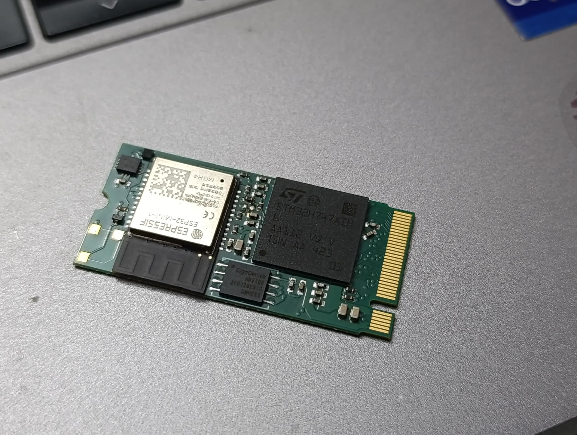
Soon, I needed dedicated hardware. This wasn’t a problem, until I realized the STM32 chip’s BGA package forced me into a big expensive 6-layer PCB just to properly fan out all the connections. I started analyzing the possibility of modular design. This would reduce the cost for this project and also develop a module easy to integrate in future projects.
To bring the cost down, I decided to create a small M.2 module with the BGA chip. This would allow the main PCB to be a much cheaper 4-layer board. The plan worked—it cut my prototype costs by about 30%!
I kept working on the code in my free time, learning proper software architecture along the way.
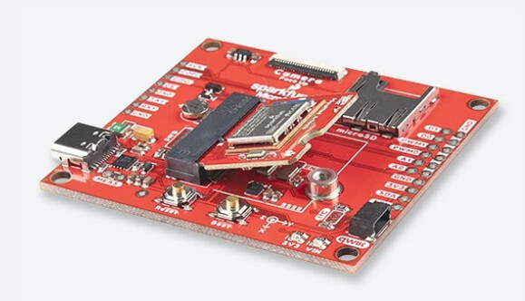
The “Aha!” Moment: Discovering MicroMod
Image from the SparkFun website
Then, about two months ago, everything changed. I was browsing the web when an ad for a SparkFun MicroMod module popped up. The promise of a standardized ecosystem, compatibility with many carrier boards, and a tiny 22x22mm footprint immediately caught my attention.
After a few hours of reading the documentation, I was sold. I knew I had to completely revamp my module.
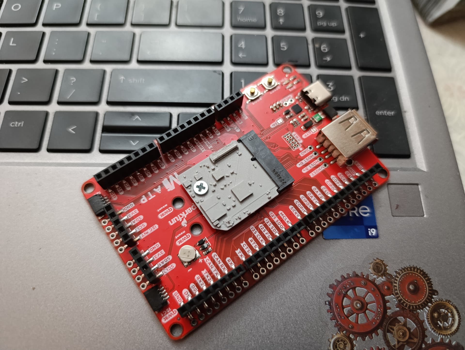
A New Vision: Going All-In on MicroMod
I decided to pivot my design and make it a no-compromise MicroMod module. My goals were:
-
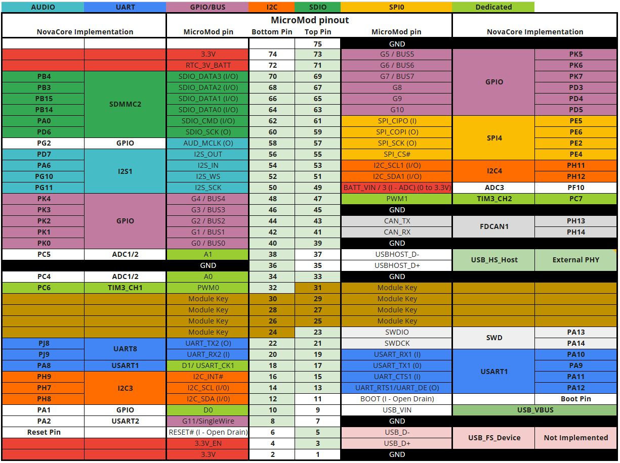
Full Compatibility: I switched from an M-key to an E-key M.2 connector and redesigned the pinout to be fully MicroMod compatible .
-
Powerful Features: I wanted to pack in features that I, as a developer, would want. This meant:
-
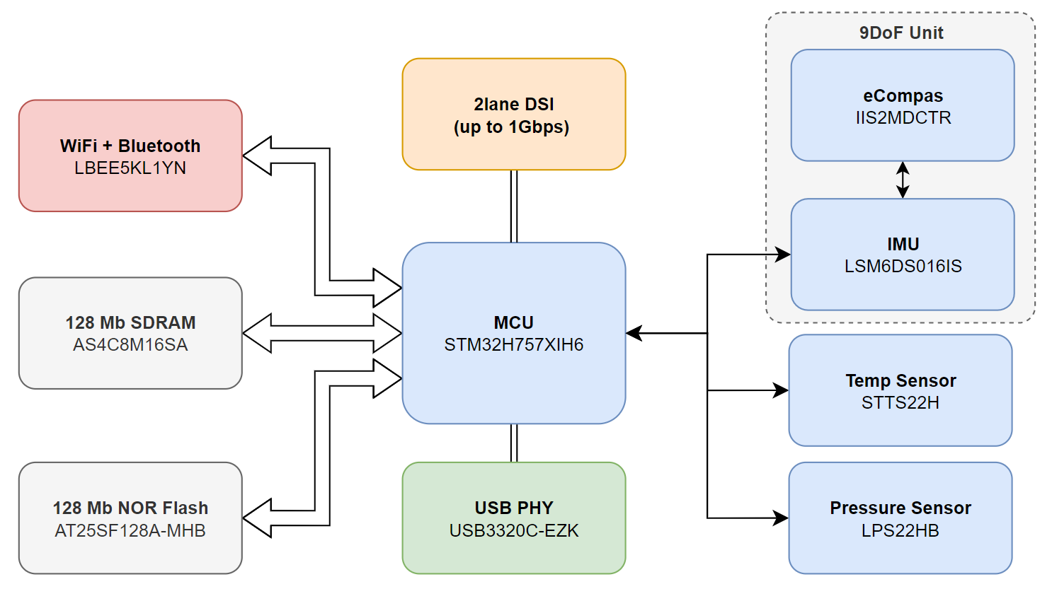
Improve Wireless Connectivity: A Murata Wi-Fi + Bluetooth LE module was a must.
-
Add Memory: I added 16MB of external SDRAM to enable complex IoT tasks and even run Edge AI applications.
-
Integrated Sensing: Since there was space, why not? I integrated a full suite of ST sensors:
One of the most exciting parts is the sensor integration. The IMU and eCompass are configured so the IMU can directly sample the eCompass and perform sensor fusion internally. According to ST, this should allow it to output true 9DoF quaternions right from the hardware—a feature I can’t wait to test!
And that’s how we got here. It started as a cost-saving measure and evolved into a powerful, feature-packed compute module for an ecosystem I’m incredibly excited to be a part of.