ARM 7 is the oldest and furthermore has the biggest support, ppl have used it and they can help me to use it as well. If I would buy a newer processor I don’t think I would get that much help.
Also, leon I have applied to ur group please accept me. Also U haven’t commented on my board is it any good?
edit: I just joined the lpc yahoo group and on the files section there is only 1 design file which is a rar containing unknown files extensions.
It looks like you are connecting the caps in series between the Vdd and the uC pins. They should be in parallel. You can however connect them all together, as long as there are caps sufficiently close.
Where is the crystal?
I may have been mistaken about the pullups on the JTAG, but I am very sure that you need them on /RESET and P0.14.
I won’t say that this project is impossible at your experience level, because I designed my first ARM7 circuit without much knowledge either, but it’s gonna be hard.
There are several PCB designs in the LPC2000 group files section. You should get plenty of ideas from them. Also look at commercial boards like those from Olimex. The PCB layouts aren’t available but you should be able to copy the schematic and the component placements.
You use WinRAR to uncompress .rar files!
The latest effort has just as many problems as previous ones. Why don’t you put the decoupling capacitors close to the chip? Putting them on the underside might help.
if I put them closer than the wires for the other pins would have no space and overlap… But if you consider that the processor has 6mmx6mm dimensions it isn’t that far…
I know it is a rar but inside the rar there are some strange files extensions like .gtp
would you mind to tell me which specific files to download? Coz I cant find them…
tried my best, I haven’t added the crystal yet, because I don’t know where and how to connect it. On eagle library the crystal has 4 pins I thought it only had 2 pins… anyways, if anyone has any lbr file or can tell me how to connect them I would appreciate it… I have finished!!! I think… The wires overlap and overall its a really bad board any ideas? What to fix? and what to add?
d4n1s:
tried my best, I haven’t added the crystal yet, because I don’t know where and how to connect it. On eagle library the crystal has 4 pins I thought it only had 2 pins… anyways, if anyone has any lbr file or can tell me how to connect them I would appreciate it… I have finished!!! I think… The wires overlap and overall its a really bad board any ideas? What to fix? and what to add?
Any suggestions?
Crystals come in 2 and 4 pin packages, but the 4 pin packages generally have 2 pins which don’t need to be connected.
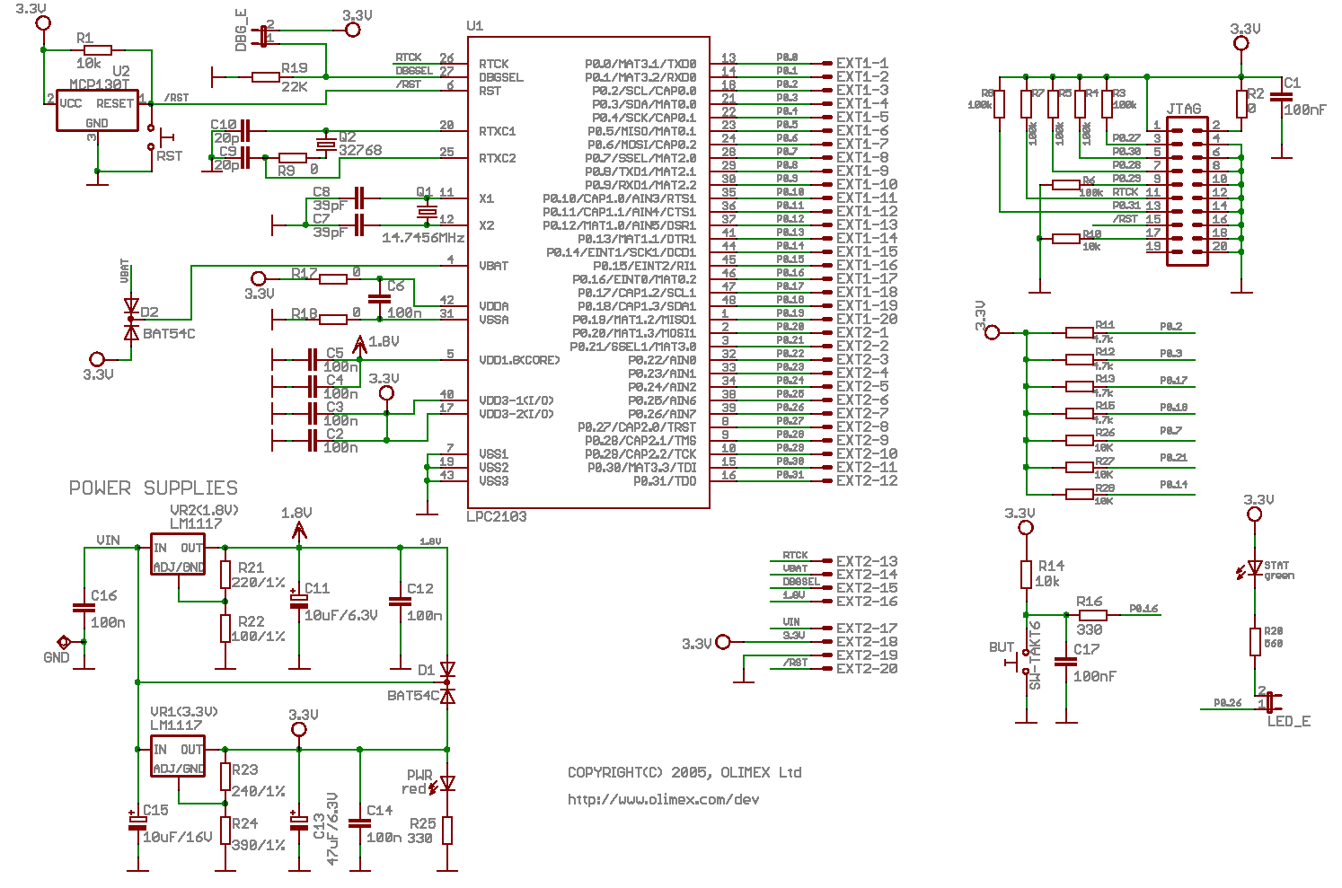
Really, this is way over your head. Start with something simpler or buy a small board. For reference, all of the Olimex boards have schematics available for them. Use them to check your design. I have no idea what chip your using, but for example, the LPC2103 header board schematic:
I have LPC2138 Here is another schematic… I will have to add that I have seen a board of arm7 that a guy didn’t used any of those u mentioned… and he managed to interface a cmos camera with it that could track objects… anyways here is a schematic http://www.2shared.com/document/fXCeCAW … matic.html
Tell me if this is any better or suggest me another schematic… I have searched on ur site leon and couldn’t find any schematic for LPC2138