
I don’t know what I am doing wrong but there are random characters ont he bottom instead of the numbers that are supposed to show
Looks like whatever USB to serial adapter you’re using is dropping characters or corrupting data. Try dropping the serial speed in the sketch and un the IDE to 57600 and see if that helps.
You could set the baud to something real low to be sure as well, like 9600. Like YellowDog mentioned, you’ll need to alter both the sketch & the drop-down selection in the serial monitor
I tried setting it really low to 9600 like the original heart monitor guide said but it did not work
Did you set both the sketch and serial monitor to 9600?
Please post the revised sketch, not a screen shot, using code tags (<> editor button).
/******************************************************************************
Heart_Rate_Display.ino
Demo Program for AD8232 Heart Rate sensor.
Casey Kuhns @ SparkFun Electronics
6/27/2014
https://github.com/sparkfun/AD8232_Heart_Rate_Monitor

The AD8232 Heart Rate sensor is a low cost EKG/ECG sensor.  This example shows
how to create an ECG with real time display.  The display is using Processing.
This sketch is based heavily on the Graphing Tutorial provided in the Arduino
IDE. http://www.arduino.cc/en/Tutorial/Graph

Resources:
This program requires a Processing sketch to view the data in real time.

Development environment specifics:
	IDE: Arduino 1.0.5
	Hardware Platform: Arduino Pro 3.3V/8MHz
	AD8232 Heart Monitor Version: 1.0

This code is beerware. If you see me (or any other SparkFun employee) at the
local pub, and you've found our code helpful, please buy us a round!

Distributed as-is; no warranty is given.
******************************************************************************/

void setup() {
  // initialize the serial communication:
  Serial.begin(9600);
  pinMode(10, INPUT); // Setup for leads off detection LO +
  pinMode(11, INPUT); // Setup for leads off detection LO -

}

void loop() {

  if((digitalRead(10) == 1)||(digitalRead(11) == 1)){
    Serial.println('!');
  }
  else{
    // send the value of analog input 0:
      Serial.println(analogRead(A0));
  }
  //Wait for a bit to keep serial data from saturating
  delay(1);
}
I got it to show the number on the bottom instead of the random characters but then when I open the serial plotter it does not show waves.
Again, did you set the serial monitor and serial plotter to 9600 baud?
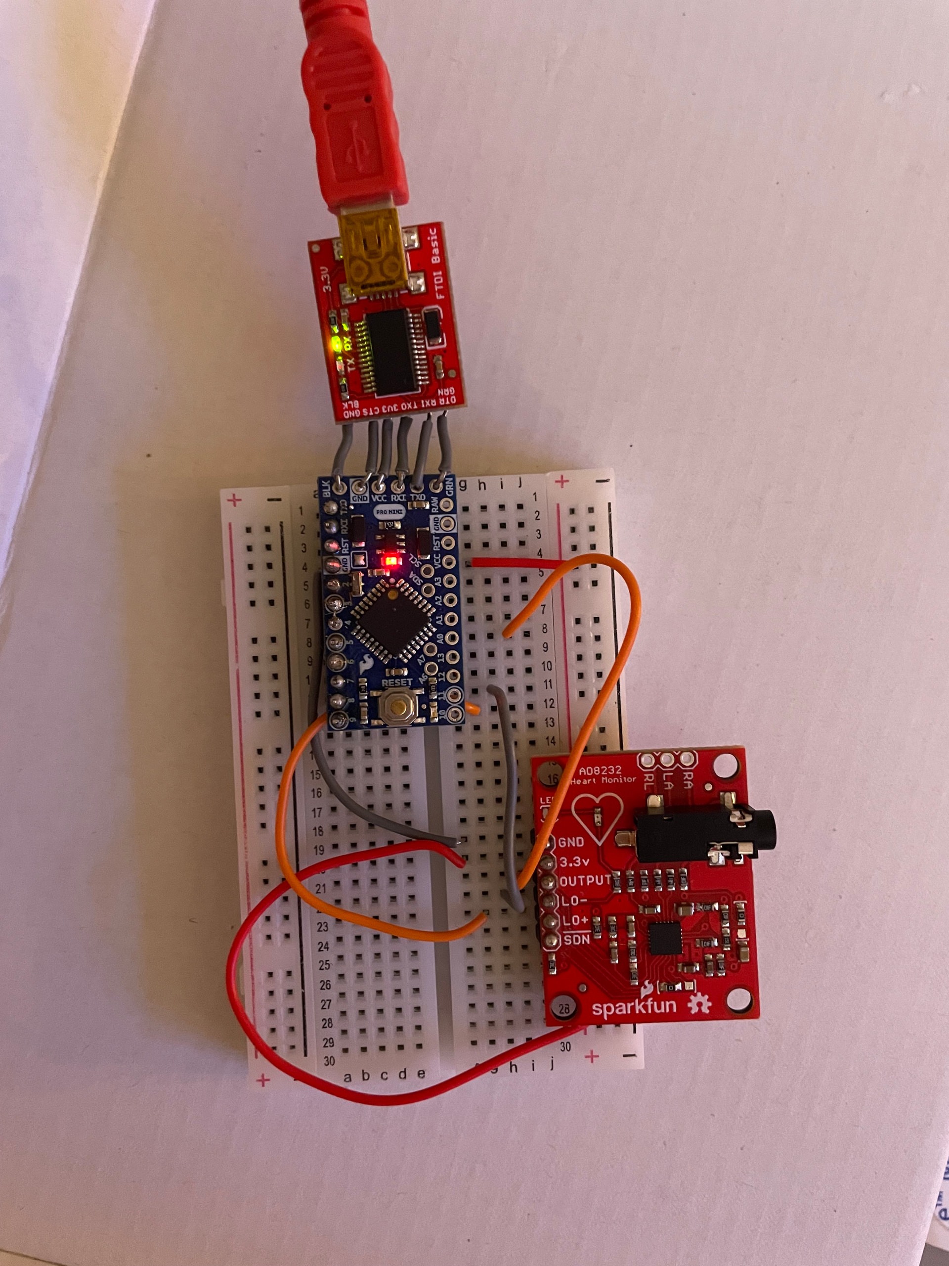
Since there are no header pins soldered to the MCU board on the side shown below, how are the four wires below supposed to be connected, and what do they do?
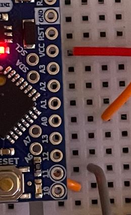
Please post a pic of a hand-drawn wiring diagram showing all the connections.
I’m not seeing any connection to pins A0,D10,D11 or VCC.
You will need to solder header pins to the Pro Mini board, in order to make the required connections.
Unfortunately, the Getting Started or Hookup Guide for the Pro Mini seems to be missing, or else the link to it on the Pro Mini product page is broken.
Look for a general soldering tutorial.