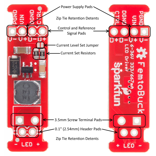
I need two femtobucks converted to 1A, any images/examples of what a proper modification looks like?
This thread says to add a third resistor but the hookup guide says to replace the resistors.
I need two femtobucks converted to 1A, any images/examples of what a proper modification looks like?
This thread says to add a third resistor but the hookup guide says to replace the resistors.
The default is replacement; you’d replace the 0.3 Ohm ones with 0.1 Ohm and be good to go…the linked thread is in the uncommon case that you do not plan to replace the resistors and instead add a third in parallel. Either should yield the desired result
You can solder the 3rd 0.3 resistor in parallel https://cdn.sparkfun.com/assets/4/a/3/d/0/femtobuckv13.pdf
https://cdn.sparkfun.com/assets/learn_tutorials/4/3/0/13716-02.png or replace the ‘current sense resistors’ pictured with 0.1 
FWIW I think replacement is simpler
Thanks Russell. So just remove both resistors and put one 0.1 on one of the pads?
Yep - The left one is R1, the one you’re after…in theory you could just swap it only but I imagine that could be tricky with the other one in the way
Hey Russell…I went to change out the resistor today and pulled two pads off. Any tips to make the change easier or not really feasible to do by hand? I was using a really small tip to get to the ends but dont have tweezer tips to heat both sides.
EDIT: I actually was able to scrape off some mask right behind the pad and placed the .1 ohm resistor. Its measuring .08-1.1ohm from VIN to the far side of the resistor so I think I was able to save it.
Nice! That was going to be my suggestion…scrape off some solder mask with something slightly rough (dremel, etc) and wire/tap into the trace
Good work! Those are very small and fiddly