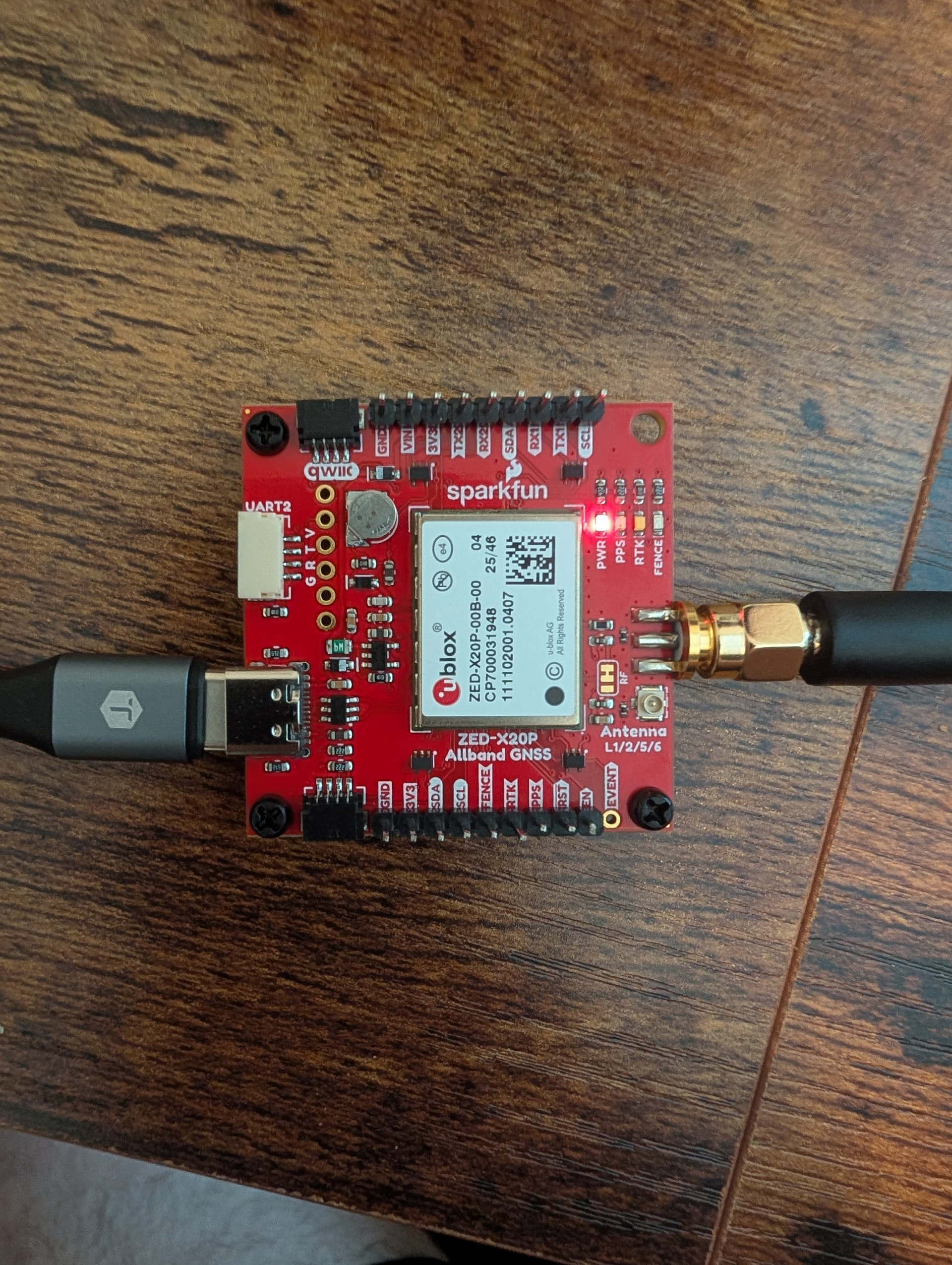
I’m using a ZED-X20P and I think I might have some internal interference. I recently bought the new module to test as a potential upgrade to my surveying set up that I use with my ZED-F9P. I am getting an agc that is pegged to 7998 across all three bands. A jam ind of 60 on the L5 band and my gps is not tracking satellites. I have evaluated in ucenter and it looks like the cw suppression is 90% for the L5 channel. I haven’t been able to make any progress in getting the new chip to work.
CGPS is reporting a fix mode of zero which and upon inspection of the nmea sentences I have some malformed sentences. This is the gpsd output as well as screenshots of the trouble shooting steps I’ve been working on.
Are you using a SparkFun ZED-X20P board? Which antenna are you using? Is the antenna outside, with a clear view of the sky? Please post a photo of your ZED board and its connections.
Thanks for the response. I am using a sparkfun zed-x20p board. I am also using the (SPK6618H) antenna also from sparkfun. It is outside with an unobstructed view of the sky.
Do you see the same level of interference when the X20P is connected direct to your laptop, compared to the Pi (if it is a Raspberry Pi?)?
Could you try a different power supply for the Pi configuration - just in case your plug-in power supply is causing the noise? Maybe try a USB Battery Pack, if you have one.
If you move the X20P away from the Pi, does the noise reduce?
From top post looks to be HPG 2.02, most current available would be HPG 2.10, but probably not the issue.
UBX-MON-SPAN would provide a spectrum analysis, if there are specific bands or harmonics. A SeeSii tinySA ULTRA+ sweeping 1.1 to 1.6 GHz using the little stubby antenna close to the boards can also be illustrative. Perhaps emissions from MCU or DDR memories.
I’d create some physical separation between the X20 board and the RPi
Thank you all for the responses. I removed the zed-x20p from the case so that it is in a benchtop configuration and took photos of the SMA soldering as well as the soldering I did to get access to the output.
I ran the MON-SPAN on my computer and got the integer array but I’m not sure how useful that would be to post here. Obviously it could be my soldering job that damaged the board but I wanted to ensure that I had exhausted all resources before getting another F9P.
This is the MON-RF output when it is on my desk. Still reporting bad NMEA senteces
Thanks for those photos! That soldering looks fine. I’m worried we’re missing something. We’re in a good spot because you have a working F9P to test against.
Have you used this particular antenna and cable with your F9P? Can you see any satellites? I’m trying to eliminate the antenna/cable as the potential issue.
Do you have a DMM that you can probe the center pin of the SMA connector on the X20P breakout? It should show 3.3V DC. If not, we have an antenna power problem.