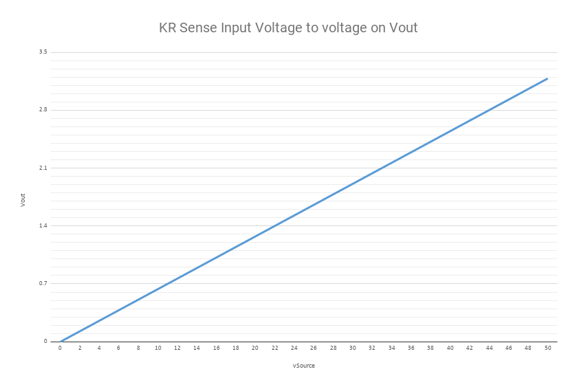
I am using the KR Sense Current and Voltage Sensor to log a current and voltage across a load for equipment testing. On the product page (https://www.sparkfun.com/products/16408), graphs are given to get the voltage and current transfer functions. From those graphs, you can get the approximate transfer functions Vin = (22/1.4)Vout and Iin = (52/1.9)Iout. I’ve found the transfer function valid for the voltage output, for example I got a Vout = 0.318 V when Vin = 5 V and a Vout = 0.636 V when Vin = 10 V. The problem arises when trying to use the current sensor, I don’t get any voltage output from it. I can’t figure out why I wouldn’t get any voltage reading. Using a 50 ohm load resistor, I only get a few hundred mA through the sensor, is that too little of a current? I’m not sure if there is a minimum current as there is no datasheet provided. Even when I run the sensor straight through my power supply at 2 A, I’m not getting any output from the Iout. Any suggestions on troubleshooting?
I’d guess that 2A is too low for good linearity https://cdn.sparkfun.com/assets/6/7/3/4 … ge_90A.png; can you try something higher (maybe ~20A?) and see if it roughly correlates to the chart/graph? It looks like it should be ~1.5 or so (@20A)
I just tried 9 A and it took around 30 seconds to slowly go from 0.15 to 0.19 where it leveled out. Though I got a reading, according to the graph that would correspond to an input current of about 5 A. The power supply I’m testing with maxes at 10 A which is why I can’t go higher right now, but even when I get a reading it’s wrong.
Even when I run the sensor straight through my power supply at 2 A, I’m not getting any output from the Iout
What do you mean by this? You set the power supply for 5 volts and 2 amps and connect it to the sensor? What load do you have attached to the sensor with these settings on your power supply?
Also, how are you measuring the voltage on the Iout pin and what two points are you measuring across?
Lastly, how are you measuring the current you’re putting through the sensor? If it’s the amp meter on your power supply, how do you know it’s accurate?
Yes set the power supply to 5 volts and 2 amps with no load just straight through the sensor.
OK, so that means you’re not passing any current through the sensor so you should be reading zero volts between ground and Iout. You need to pass the current through the sensor to read it. The 2 amp setting on your power supply just means it can deliver up too 2 amps, not that it’s delivering that now.
I think you’re going to need a bigger power supply and load, high current sensors like these are not terribly accurate at low currents, the signal ends up being really small and gets lost in the noise. A 20-30 amp load would be better, at exactly 28 amps of load through the board you should see exactly (or really close to) 1 volt between gnd and Iout.
I tried the KR Sense 45A, put over 3 amps through it using a load resistor and got 000.0 mV result, I double checked all my connections, nothing wrong, this product surely requires a lot of current to give a reading.
This product does not seem to fit in with Sparkfun, what project would you make using components purchased from Sparkfun that would be pumping such high currents?
I say this because to save anyone else that doesn’t know any better the headache of purchasing one of these thinking it is going to be useful in a low volt/low current project, it is not.
I don’t have a picture at the moment, but I connect from power source to the +IN and load to +OUT and ground from source + to GND and from GND to source -
I measure the scaled volts from Vout and the GND next to it, and current from Iout and the GND next to the Vout.
The supply should be connected to +IN (positive) and GND (negative). It should be set to a voltage between 3v and 60v and the current limit (if it has one) should be more than what the load will draw at your supply voltage
The load should be connected to +OUT and GND and should draw between 3 and 10A at your supply voltage if you are using the 45A board. These connections should use the gold GND bus with three holes at the top of the board.
The meter should be connected between Iout (positive) and GND (negative)
I ended up purchasing a couple of shunts: Fielect 10A 75mV DC Current Meter Shunt Resistor
I put together a set of parallel power resistors and ran a few different current values through the shunt from .04A to 1.5A and the mV readings were near perfect on the multimeter based on the 75mV at 10A.
On my ADS1115 using differential read of input from my power supply set to 0.01V, over a set of 50 samples I got a high of 10.406mV, a low of 10.187mV, with an avg of 10.310mV which translates to a swing of 13mA plus or minus, my bench power supply is a budget priced Korad so it may have contributed to the noise.
I was just hoping to get reliable readings to 100mA from the shunt so I am happy with a +/- 13mA