Hello, I was wondering if anyone might be able to point me in the right direction a small project I am working on. What I am trying to do is construct a crankshaft balancing machine to balance small V-twin crankshafts. It will be constructed from aluminum and consist of a rigid frame that suspends a square cradle from each corner. The cradle will be fitted with 4 bearing located in the center of the cradle ( 2 on each side) that will hold the crankshaft. A counterweight will be assembled and attached to the rod journal to simulate the imbalance of the rods, pistons, rings, bolts, etc, etc. With the crankshaft sitting on the cradle, the crank is spun at 500 rpms. The cradle is able to move in one axis, indicating imbalance.
So my take on this is I could use a accelerometer attached to the cradle to get a reading using a voltage gauge
( higher voltage=higher imbalance). I would also have to be able to trigger a superbright LED to act as a strobe at the peak voltage. But since the voltage would drop each time an adjustment to balance was made and improved, I would need a comparator circuit? I know there is a way to make it work but I have no clue as to what parts are needed and what else is needed to make it all work together. If I could find a schematic or if someone could sketch up a schematic, that would be awesome, I could go from that. I can solder and assemble the circuit, just not sure what I need. Analog is fine or I could go digital and use an oscope to see, it’s really just a comparitive tool. Add weight, remove weight, see if it’s better or worse. Wash rinse repeat. It won’t be perfectly balanced due to the design of the engine but much better than nothing.
Thanks for any help you could lend and if there is any details needed, let me know.
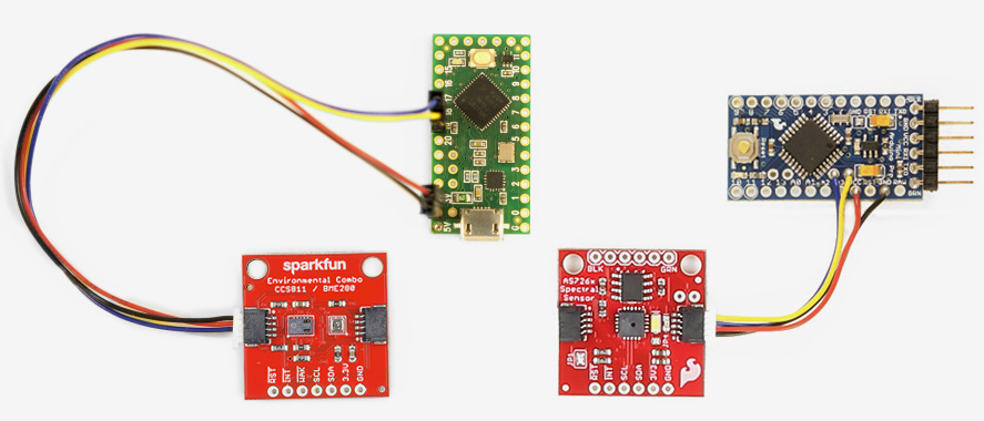
Any LED of your choice wired to one of the PWM pins on the mini (the ones with the circles around the pads)
Qwiic is my preferred way to go these days just for fewer wires to strip and solder. And you can more easily break projects down for re-use.
You’d need to filter the XYZ data and come up with a total vector value for that moment. I’d store that value to EEPROM as the value changed greater than a certain amount (so that I’m not constantly writing to EEPROM). Or perhaps you just want to power the board and only care about the min accel value since power on… skip the EEPROM stuff then.
As the total vector decreased by some defined amount (found by testing) I’d increase the brightness of the LED. I kind of like your strobe idea tho. It may be easier to see a faster blinking LED than merely a softer or brighter LED (I know it’s all PWM but whatever). Soldering to the PWM capable pin gives you either option (blink or brightness).
Sorry, I can’t point you towards a schematic, just me spit balling.
Hey Sparky, thanks for the kind words about my idea being cool. I’m thinking analog just because it may be a little simpler for some one like me, but will look at digital as a viable option. Seems a lot of this digital stuff is pretty simple once you can get your head around how it works. I have done some research and think a comparator circuit using an Op Amp might fit in my project. There was a fellow on YouTube that showed a circuit using a potentionmeter to vary the threshold voltage. That would be useful to attenuate the signal from the accelerometer, meaning when the crank is way out you could turn the threshold up and as the crank became more balanced, the threshold could be turned down as the voltage input drops.
Not trying to get off topic here, but I wonder in a piezo sensor would be a better fit for what I’m trying to do vs. an accelerometer?