Hello Paulvha,
So you think it can be put back to the external power supply and proceed with reading the tags?
Thanks,
Hello Paulvha,
So you think it can be put back to the external power supply and proceed with reading the tags?
Thanks,
yes.. it should work..
btw the different bytes exchanged means the following:
********************************* SENDING DATA *********************************
ff 00 03 1d 0c
Sending request to get version info (0x03): TMR_SR_OPCODE_VERSION
******************************** RECEIVED DATA *********************************
ff 14 03 00 00 23 01 06 00 38 00 02 01 20 23 11 22 02 01 03 2e 00 00 00 10
Received version information :
boot loader version 23 01 06 00
hardware version 38 00 02 01 TMR_SR_MODEL_M7E
firmware date 20 23 11 22 (yy yy mm dd)
firmware release 02 01 03 2e
protocol bits 00 00 00 10 supported protocols: PROTOCOL_GEN2
********************************* SENDING DATA *********************************
ff 04 06 00 01 c2 00 a4 60
Sending request to set baudrate to 115200 (0x06): TMR_SR_OPCODE_SET_BAUD_RATE
********************************* SENDING DATA *********************************
ff 00 03 1d 0c
Sending request to get version info (0x03): TMR_SR_OPCODE_VERSION
******************************** RECEIVED DATA *********************************
ff 14 03 00 00 23 01 06 00 38 00 02 01 20 23 11 22 02 01 03 2e 00 00 00 10
Received version information :
boot loader version 23 01 06 00
hardware version 38 00 02 01 TMR_SR_MODEL_M7E
firmware date 20 23 11 22 (yy yy mm dd)
firmware release 02 01 03 2e
protocol bits 00 00 00 10 supported protocols: PROTOCOL_GEN2
********************************* SENDING DATA *********************************
ff 02 93 00 05 51 7d
Sending request to set tag protocol (0x93): TMR_SR_OPCODE_SET_TAG_PROTOCOL
Setting to tag protocol 5 PROTOCOL_GEN2
******************************** RECEIVED DATA *********************************
ff 00 93 00 00
Received status word: 0x0000 (TMR_ALL_GOOD_OK)
********************************* SENDING DATA *********************************
ff 02 91 01 01 70 3b
Sending request to set search list for antenna (0x91): TMR_SR_OPCODE_SET_ANTENNA_PORT
setting txPort: 0x01 rxPort: 0x01
******************************** RECEIVED DATA *********************************
ff 00 91 00 00
Received status word: 0x0000 (TMR_ALL_GOOD_OK)
********************************* SENDING DATA *********************************
ff 01 97 01 4b bc
Sending request to set region code (0x97): TMR_SR_OPCODE_SET_REGION
setting to : 0x01 (NA North America)
******************************** RECEIVED DATA *********************************
ff 00 97 00 00
Received status word: 0x0000 (TMR_ALL_GOOD_OK)
********************************* SENDING DATA *********************************
ff 02 92 01 f4 40 ad
Sending request to set READ power (0x92): TMR_SR_OPCODE_SET_READ_TX_POWER
set power to 500
******************************** RECEIVED DATA *********************************
ff 00 92 00 00
Received status word: 0x0000 (TMR_ALL_GOOD_OK)
Hello Paulvha,
Switched the 5V and GND connections to the external Power supply (and made sure GND of 3V3 and 5V are connected).
Sorry to say the “Module Failed to Respond - Check Wiring.” message has returned.
Very confusing!
Another observation:
Please note there are slight differences in the Time out. It indicates “Incomplete response”.
configsip: 0, SPIWP:0xee
clk_drv:0x00,q_drv:0x00,d_drv:0x00,cs0_drv:0x00,hd_drv:0x00,wp_drv:0x00
mode:DIO, clock div:1
load:0x3fff0030,len:4980
load:0x40078000,len:16612
load:0x40080400,len:3480
entry 0x400805b4
sendCommand: [FF] [00] [03] [1D] [0C]
Time out 1: No response from module
sendCommand: [FF] [04] [06] [00] [01] [C2] [00] [A4] [60]
sendCommand: [FF] [00] [03] [1D] [0C]
Time out 1: No response from module
Module failed to respond. Please check wiring.
ets Jul 29 2019 12:21:46
rst:0x1 (POWERON_RESET),boot:0x13 (SPI_FAST_FLASH_BOOT)
configsip: 0, SPIWP:0xee
clk_drv:0x00,q_drv:0x00,d_drv:0x00,cs0_drv:0x00,hd_drv:0x00,wp_drv:0x00
mode:DIO, clock div:1
load:0x3fff0030,len:4980
load:0x40078000,len:16612
load:0x40080400,len:3480
entry 0x400805b4
sendCommand: [FF] [00] [03] [1D] [0C]
Time out 2: Incomplete response
sendCommand: [FF] [04] [06] [00] [01] [C2] [00] [A4] [60]
sendCommand: [FF] [00] [03] [1D] [0C]
Time out 2: Incomplete response
Module failed to respond. Please check wiring.
Check the wiring again, else switch back and (re)start from there.
step-by-step.. make clear note on what you change. maybe half/loose/bad wiring, bend the connection pins a little.. the patch boards are know to get weaker in the connection. Maybe it is the power supply..
There is no responds.. maybe bad wire connection.. won’t be the first time..
Hello Paulvha,
Thanks, Will keep working on cleaner & solid connections and keep an eye on the Power supply.
Will keep the sketch the same and continue. Will keep you informed.
Thanks for the support.
Chandra
Hello Paulvha,
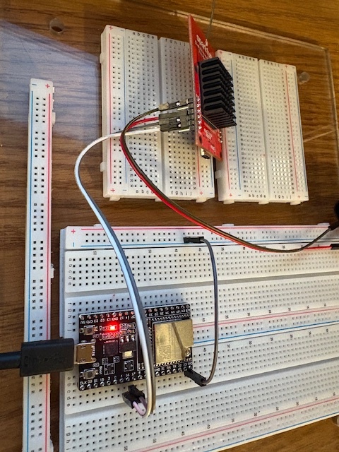
I removed the M7e board from the breadboard and connected it directly to the soldered to the header pins as shown in the attached picture. The connection now is good.
Replaced the breadboard 5V supply with my Lab power supply (GW Instek DC Power Supply) as shown in the attached picture.
The board worked fine and was able to read tags with the example sketches.
The problem of the “Module Failed to respond” keeps recurring now and then.
There is something definitely “flaky”. I will keep trying for some more time to identify the root cause.
I would also like to explore the possibility of sending the M7e to you to check it out.
Thanks for all your help.
Chandra
Screen shot of the Serial monitor below:
Initializing…
Module failed to respond. Please check wiring.
ets Jul 29 2019 12:21:46
rst:0x1 (POWERON_RESET),boot:0x13 (SPI_FAST_FLASH_BOOT)
configsip: 0, SPIWP:0xee
clk_drv:0x00,q_drv:0x00,d_drv:0x00,cs0_drv:0x00,hd_drv:0x00,wp_drv:0x00
mode:DIO, clock div:1
load:0x3fff0030,len:4980
load:0x40078000,len:16612
load:0x40080400,len:3480
entry 0x400805b4
Initializing…
Module failed to respond. Please check wiring.
Can you post some clear up-close photos of the soldering? It’s hard to tell but the m7e looks like it might have dark spots or maybe flux or something?
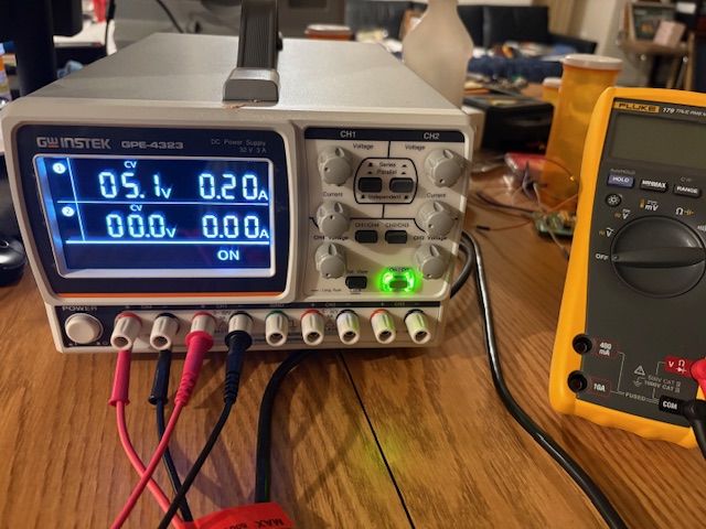
Is your power supply only setup to deliver 0.2 amps? I’d up that to 2.0 and see if things get better.
The M7E, like the M6E, is VERY sensitive to a good power supply. As soon as you start reading it works in “bursts”. A standard wall wart will NOT do it. You need a “lab” power supply that has enough capacitor power to handle these bursts. Many articles about it on this forum.
For the intitial start-up with connecting and only to read the hardware / firmware should not be a problem. Instead of using external supply, just connect directly to the ESP32. The less wires, the better. Also try with lower RFIDspeed (e.g. 38400).
Does the M7E work without problems on USB with the URA from Jadak/Thingmagic, then your M7E should be good. Working with USB is just adding the on-board USB/Serial convertor.
Hello,
Thanks for your suggestion and sorry for the delay in responding.
The current limit is set at 1.3 Amps. What you see in the picture is the actual current draw at that time.
The unit is working fine, and I will switch to a separate power supply next month.
Thanks,
Chandra