M7e Hecto with ESP32 - "Module Failed to Respond - Check Wiring" error message

Hello Community,

First time here.

I am interfacing a M7e Hecto with a ESP32. The M7e Hecto works fine when using USB and reads the rfid tags well.

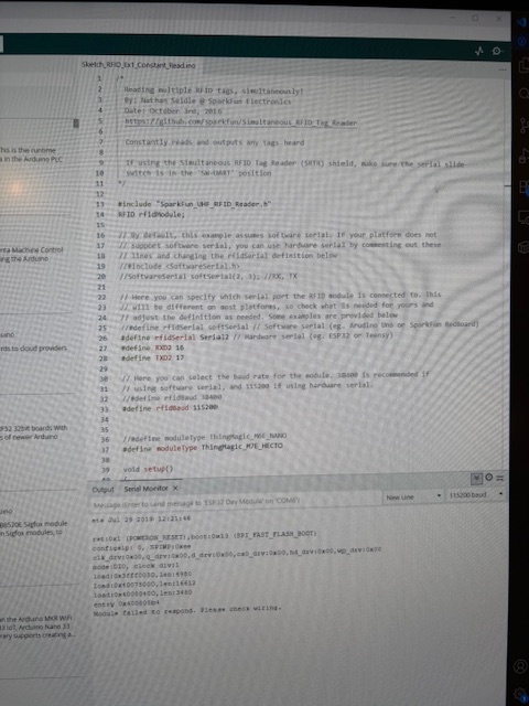
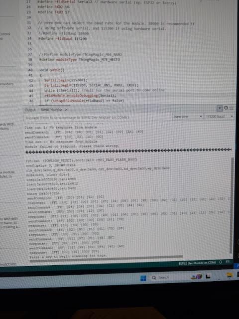
When I try to use the PTH UART serial connection and use the Constant Read sketch, I get the message “Module failed to respond. Please check wiring”.

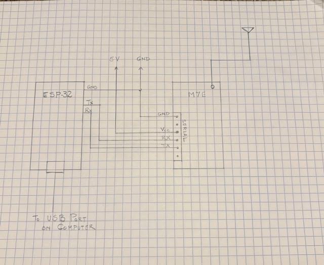
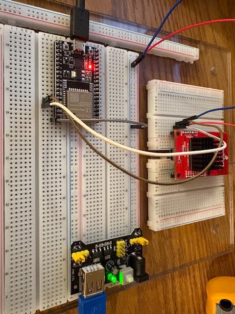
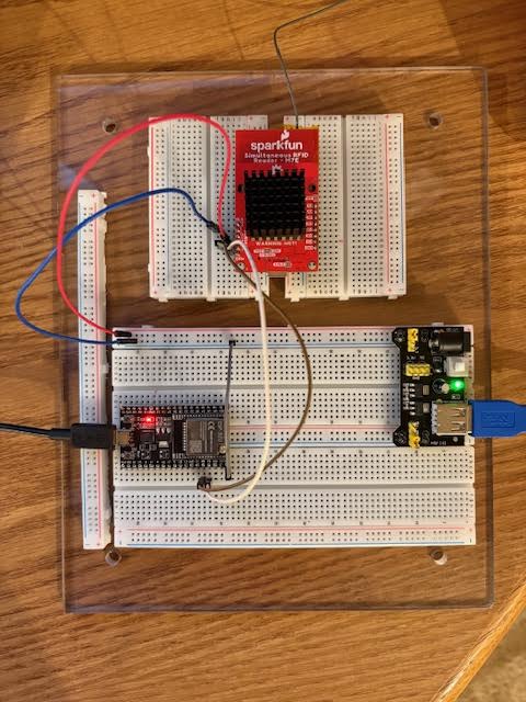
I have the following connections between the two:

  • ESP32 (Tx, Rx) connected to M7e Hecto (Rx, Tx).

  • M7e Hecto powered by a separate power supply - 5V and GND connected.

  • Connected GNDs together (3V3 and 5V supplies).

I have verified that the Arduino Library version is the latest 1.0.2.

The slide switch is on SER position.

“Constant Read” sketch fails with the message “Module Failed to Respond - Check Wiring”.

Here are the first few lines of the sketch:

/*
Reading multiple RFID tags, simultaneously!
By: Nathan Seidle @ SparkFun Electronics
Date: October 3rd, 2016

Constantly reads and outputs any tags heard

If using the Simultaneous RFID Tag Reader (SRTR) shield, make sure the serial slide
switch is in the ‘SW-UART’ position
*/

#include “SparkFun_UHF_RFID_Reader.h”
RFID rfidModule;

// By default, this example assumes software serial. If your platform does not
// support software serial, you can use hardware serial by commenting out these
// lines and changing the rfidSerial definition below
//#include <SoftwareSerial.h>
//SoftwareSerial softSerial(2, 3); //RX, TX

// Here you can specify which serial port the RFID module is connected to. This
// will be different on most platforms, so check what is needed for yours and
// adjust the definition as needed. Some examples are provided below
//#define rfidSerial softSerial // Software serial (eg. Arudino Uno or SparkFun RedBoard)
#define rfidSerial Serial1 // Hardware serial (eg. ESP32 or Teensy)
#define RXD1 16
#define TXD1 17

// Here you can select the baud rate for the module. 38400 is recommended if
// using software serial, and 115200 if using hardware serial.
//#define rfidBaud 38400
#define rfidBaud 115200

//#define moduleType ThingMagic_M6E_NANO
#define moduleType ThingMagic_M7E_HECTO

void setup()
{
Serial.begin(115200);
Serial1.begin(115200, SERIAL_8N1, RXD1, TXD1);
while (!Serial1); //Wait for the serial port to come online

if (setupRfidModule(rfidBaud) == false)
{
Serial.println(F(“Module failed to respond. Please check wiring.”));
//Serial.println(“setupRfidModule returned False”);
while (1); //Freeze!
}

Can someone please help me in identifying the issue.

Thanks,

Are the connections soldered? Can you share a photo of the wiring/setup?

How is the m7e being powered? If you have the esp32 also powering the reader then that is likely the issue Basic Assembly - SparkFun Simultaneous RFID Reader - M7E Hookup Guide

Hello Russell,

Thanks for getting back to me.

As you can see, the headers are soldered to the boards and pushed on to the breadboard.

I have attached a connection diagram, and two photos of the setup.

I have tried swapping the TX and RX without any success.

I am confirming the UART slider switch is on “SER”.

Please let me know if you want me to do any other checks.

Thanks, and appreciate your time.


1 Like

Connections look good…I’m suspicious of the usb board there

Can you swap to powering via the barrel jack instead of the blue usb cable? What are the specs on that converter?

The Power supply voltage regulator is a AMS1117, and is rated for 5V /1 Amp.

Even if I power it through the barrel jack, it will be the same voltage regulator chip will feed the M7E.

If you suspect it is the 5V power supply, I will try a different one and will get back to you tomorrow (as I have to buy a new power supply).

Thanks again for your time.

Hello Russell,

Here is the first page of the data sheet.

AMS1117.PDF.pdf (21.6 KB)

Thanks,

Right, but usb ports only supply 500mA without PD negotiation…I suspect it isn’t outputting enough amps via usb power (because it also loses some power due to inefficiencies in transforming). It’ll be supplying less power than the single usb cable setup

Let me know the results!

Hello Russell,

I forgot to mention that the Blue Cable is not connected to the USB port of a computer but to a wall plug adapter with a rating of 5V / 2.4 A.

I will still try to get another power supply module tomorrow and try again.

This problem has driven me nuts.

Thanks for your time.

Chandra

It is hard to see from the pictures, but 2 remarks:

Looking on where M7E is connected, Is that really GPIO16 and GPIO17? There are many ESP32 boards layouts, but I get the impression it is GPIO1(TX0) and GPIO3 (RX0). The layout of your board looks a lot like ESP-32 Microprocessor – DuinoKit

Is the power led on the M7E ON ? Can’t see that on the picture as it is underneath.

I have tried you sketch & modifications on my ESP32 and it works.

Hello Russell / Paul,

I am confirming that the LED is ON.

I have tried defining TXD as 1 and RXD as 3 — also with no success.

I have tried different power supply units (12 Watt) — with no success.

I am missing something for sure but cannot put my finger on it!!

Would you recommend sending the unit back to you to check it out ?

Thanks,

Chandra

can you make a clear picture, top view, of the ESP32 connection ? As a mentioned i am concerned they were to NOT connected GPIO16 and GPIO17 according to the board layout ?

Hello Paul,

I am attaching photos after I moved it to pin 16 (RXD) and pin 17 (TXD), and the results were no different.


When I had it connected in the earlier configuration of pin TX and RX, it was defined in the sketch as RXD 3 and TXD 1. Still had the same “Module failed to respond. Please check wiring.” message.

In both configurations, swapped TX and RX lines with the same error message.

Thanks,

Hello Paul,

Do I need to include the HardwareSerial library to use Serial1 or Serial2 ?

I have not seen this being used in your example sketch. Just confirming.

Thanks

Looks you now have GPIO16 and GPIO17. The RXD -3 and TXD- 1 are Serial (same as USB). So don’t use those. Indeed try to switch exchange (although the brown wire looks to be in the right position) the wires and reboot.

If no success yet :

Connect the M7E GND to the ESP32 GND and the M7E VCC to the 5V, next to the USB connector and try again. Do not use external power supply. As long as you don’t start reading, there is just a low power needed on the M7E which the ESP32 can provide. Check the power light is on the M7E.

If that does not work still to detect.

  1. adjust the Serial/USB switch forth and back again in the serial (it happened in the past it did not connect well).
  2. Else remove the power ESP32 power and reconnect. Once the M7e is “in limbo”, it stays there.

If that does not work make sure to add in setup() before if (setupRfidModule(rfidBaud) rfidModule.enableDebugging(Serial); Then re run and share the serial outcome.

Hello Paulvha,

Followed all your instructions, and the result did not change.

Confirmed the Power LED is ON.

The results with debugging enabled are as follows:

Thanks for your help. Appreciate it.

Chandra

although hard to see, there is NO responds from the m7E on the 2 requests (first and third) for the hardware/firmware information and the 2nd request is to change the baudrate. (there is no responds expected on this one).

The M7E is working, as you connected it to the USB and got it to read. It is weird.

Let’s make it is not a wire issue. Reconnect the RX / TX wires from the M7e and connect only those 2 on a different place on the patch-board. Whatever is sent by the sketch should be received in debug mode

Hello Paulvha,

Kept and jiggling the wires to make sure everything was fine. When rebooted, I has a different response this time. Please see the photo attached.

Hope this helps.

Thanks,

Chandra

can’t read it.. but it looks much better in responds. Looks it is working now.

When you now start reading for a tag.. it might bail out due to power consumption that the ESP32 can not deliver.. at least the basic communication is working

Here it is.

load:0x40080400,len:3480
entry 0x400805b4
sendCommand: [FF] [00] [03] [1D] [0C]
Time out 1: No response from module
sendCommand: [FF] [04] [06] [00] [01] [C2] [00] [A4] [60]
sendCommand: [FF] [00] [03] [1D] [0C]
Time out 1: No response from module
Module failed to respond. Please check wiring.

rst:0x1 (POWERON_RESET),boot:0x13 (SPI_FAST_FLASH_BOOT)
configsip: 0, SPIWP:0xee
clk_drv:0x00,q_drv:0x00,d_drv:0x00,cs0_drv:0x00,hd_drv:0x00,wp_drv:0x00
mode:DIO, clock div:1
load:0x3fff0030,len:4980
load:0x40078000,len:16612
load:0x40080400,len:3480
entry 0x400805b4

sendCommand: [FF] [00] [03] [1D] [0C]
response: [FF] [14] [03] [00] [00] [23] [01] [06] [00] [38] [00] [02] [01] [20] [23] [11] [22] [02] [01] [03] [2E] [00] [00] [00] [10]
sendCommand: [FF] [04] [06] [00] [01] [C2] [00] [A4] [60]
sendCommand: [FF] [00] [03] [1D] [0C]
response: [FF] [14] [03] [00] [00] [23] [01] [06] [00] [38] [00] [02] [01] [20] [23] [11] [22] [02] [01] [03] [2E] [00] [00] [00] [10]
sendCommand: [FF] [02] [93] [00] [05] [51] [7D]
response: [FF] [00] [93] [00] [00]
sendCommand: [FF] [02] [91] [01] [01] [70] [3B]
response: [FF] [00] [91] [00] [00]
sendCommand: [FF] [01] [97] [01] [4B] [BC]
response: [FF] [00] [97] [00] [00]
sendCommand: [FF] [02] [92] [01] [F4] [40] [AD]
response: [FF] [00] [92] [00] [00]
Press a key to begin scanning for tags.

yep… it now connects to the M7E and is ready to start reading. See previous remark on potential bailing out. An external supply can help to overcome that