I am trying to hook up a sparkfun microOLED to the i2C bus of the itsyBitsy M0. The OLED works fine with a redboard with a level shifter (on I2c) but when I connect it to the itsy I get very inconsistent results.
When running an i2c bus scan loop the micro OLED will show up for a few iterations then not show up for a few iterations. If I run the same code with an adafruit bme280 hooked up I get an address back on every loop, or if I have that plus the oled hooked up I get the bme address every loop and both the bme and the oled addresses every few loops.
I get the same results whether scanning the bus via the arduino IDE/cpp or via circuitPython… unless I am doing the scan The only time I get the oled address on every loop is with the redboard.
I I am attaching the itsy to the usb port of a macBook Pro; Adafruit ItsyBitsy M0 Express with samd21g18.
The itsy is supposed to need pullup resistors on the i2c lines and I’ve tried 4.7k, 2.2k and the two in series (6.9k)
I’ve been stuck on this problem for three days now, trying multiple permutations of the boards in order to isolate the problem. I’d appreciate some help in getting this working.
I didn’t see any pullups on the microOLED either but I am grasping at straws at this point.
Am still looking for help on why the board won’t consistently reply to an i2c scan inquiry from the (adafruit itsyBitsy) M0 board but will on your redboard. Adafruit suggested that the board may need a reset so I poked around the sparkfun library and saw that the reset pin is used there when initializing the board but haven’t checked into Wire.h. The following code does not get a consistent response from your board and I’d like to know why, so that I can use it… I’ve two of them sitting in a box.
Any help would be appreciated.
// initially tried to output anything to the microOled breakout from the itsyBitsy M0 but had no luck
// now just trying to find it in an i2c bus scan.... sometimes it shows up and sometimes it doesn't
#include <Wire.h>
#include <SFE_MicroOLED.h>

#define PIN_RESET 9
#define DC_JUMPER 0


#if defined(ARDUINO_SAMD_ZERO) && defined(SERIAL_PORT_USBVIRTUAL)
  // Required for Serial on Zero based boards
  #define Serial SERIAL_PORT_USBVIRTUAL
#endif

MicroOLED oled(PIN_RESET, DC_JUMPER);  // leftover from when I was trying to actually print something to the oled

void setup() {
  // put your setup code here, to run once:
Serial.begin(9600);

  while (!Serial); // Leonardo: wait for serial monitor
  Serial.println("\n------------\nI2C Scanner Aug 04");

  Wire.begin();
  //oled.begin();


}

void loop() {
  // put your main code here, to run repeatedly:
  byte error, address; //variable for error and I2C address
  int nDevices;

  Serial.println("Scanning...");

  nDevices = 0;
  for (address = 1; address < 127; address++ )
  {
    // The i2c_scanner uses the return value of
    // the Write.endTransmisstion to see if
    // a device did acknowledge to the address.
    Wire.beginTransmission(address);
    error = Wire.endTransmission();

    if (error == 0)
    {
      Serial.print("I2C device found at address 0x");
      if (address < 16)
        Serial.print("0");
      Serial.print(address, HEX);
      Serial.println("  !");
      nDevices++;
    }
    else if (error == 4)
    {
      Serial.print("Unknown error at address 0x");
      if (address < 16)
        Serial.print("0");
      Serial.println(address, HEX);
    }
  }
  if (nDevices == 0)
    Serial.println("No I2C devices found\n");
  else
    Serial.println("done\n");

  Serial.println("waiting 5 seconds to scan again");

  delay(5000); // wait 5 seconds for the next I2C scan
  Serial.println("done waiting, scanning again");

}
Hello! I’m also working on a similar project as well. I am trying to run this product: https://www.sparkfun.com/products/13003 with the given example code in I2c Mode, however I can’t seem to get it running. May I just check with you more regarding the pullup resistors? So A4 must be connected to a resistor on a breadboard then a wire from the breadboard to the micro oled? Same for A5 too.
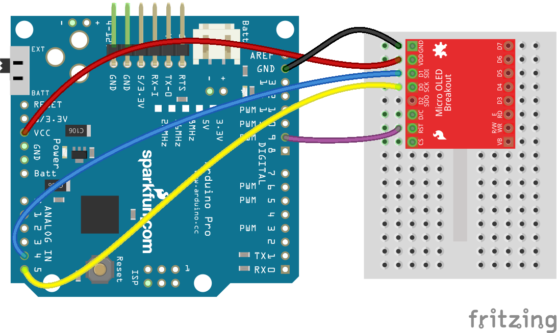
The display actually works fine without any pull-up resistors. Not sure why since none seem to be included in the schematic for the product. … the hookup guide does not include any in their diagram either. https://cdn.sparkfun.com/assets/learn_ … p_bb_1.png
If you are trying to connect via I2c make sure you have done a good job changing the jumpers (solder pads) on the back of the board… there’s a photo of my board in this thread.
Just a thought: make sure that the board selected is the Itsy Bitsy M0. It’s running at 48MHz as opposed to the Redboard’s 16 MHz, and there may be some “corrections” for this in the libraries associated with each board. I2C does have maximum speeds, so if you’re effectively trying to overclock the I2C bus things on the bus could be “flakey”.
