What do the wire colors on this motor do? I don’t see it on the datasheet. I assume there’s an M+, and M-, two square waves, a ground, and a Vcc but which color is which it’s not on the datasheet.
1 Like
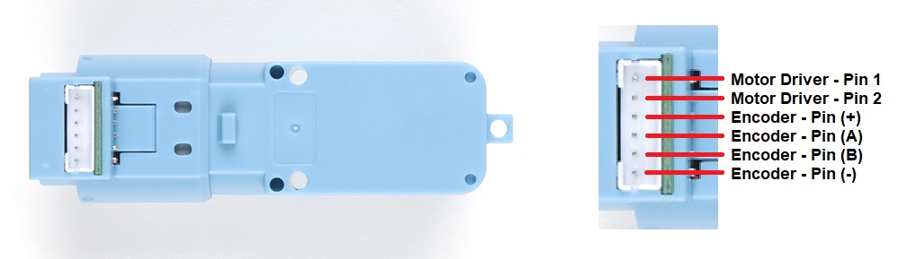
thankyou, can you tell me where each pin goes if i wanted to use an h-bridge? motor driver pin 1 and 2 go to h-bridge output 1 and 2; encoder + pin goes to Vcc? encoder - pin goes to GND? encoder pin A and encoder pin B are which squares waves on this graph…?
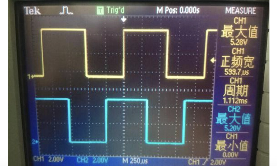
basically what i want to know is if i catch a falling edge on encoder pin A and encoder pin B is currently reading HIGH, am i spinning clockwise or counterclockwise
also can you tell me about current draw at no load and at stall torque please? need to figure out battery specs!
Motor Driver Pins 1 and 2 go to your motor driver H bridge output.
Encoder pin + goes to 3.3 or 5 volts.
Encoder pin - goes to ground.
Encoder A and Encoder B go to your sensing circuit. (or oscilloscope)
They do not show how the motor in the datasheet is connected, if you’re not getting the output you want when the motor is rotating in the desired direction, swap the A and B pins.
Unfortunately the datasheet doesn’t give any figures for current at all, you’ll need to determine those experimentally.
1 Like
Oddly I found the extra info in the mouser datasheet - I’ll get ours updated!
0.15 Nm
0.75A @ 6v (it’d be higher at a lower voltage)
For the square waves, how many periods per revolution, in other words if I detect a falling edge 20 times per second, is the full period of one revolution of the motor 0.05 seconds, 0.1 seconds, 1 second ? Something else?
No idea. If it’s not in the datasheet you will need to find it experimentally.
Edit:
Found this in the reviews, no idea if it’s accurate.
gear ratio is 1:45 and that there are 3 encoder magnets, so for 1 wheel rotation you have 3*45=135 encoder rising edges.
1 Like