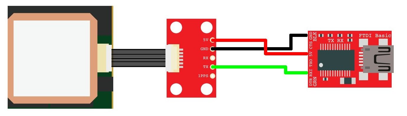
I am working on a school engineering project and my group has a question about a tutorial (https://www.sparkfun.com/tutorials/403) which hasn’t been updated for the new GPS breakout board. The tutorial has a jpg of what connections should be soldered together, however, due to us having a newer GPS breakout it is difficult to determine what connection is what (especially considering the different labeling, this is the image we are struggling with dlnmh9ip6v2uc.cloudfront.net/tutorialimages/Python_and_GPS/hardware.jpg). If an updated version of this schematic (only one we could find was http://dlnmh9ip6v2uc.cloudfront.net/dat … eakout.pdf) could be made or just described to me via email it would be very helpful. Thank you!
Hi ryanjoliva.
A lot has changed in the last 8 years since that tutorial was written.
The [old breakout used to be specific to one GPS module and the pinout was printed right on the breakout for that module. Since then, many other manufactures have released GPS modules that use the same connector, but have a different pinout. Since the [new breakout has only pin numbers rather than functions printed on it, it’s able to be use with a variety of different GPS modules.
What you’re going to need to do is check the data sheet for the GPS module you’re using to determine what the pinout is and then make your connections based on that. The data sheet should tell you what each numbered pin does and you can match that up with the pin numbers on the newer breakout board.](SparkFun GPS Breakout - BOB-11818 - SparkFun Electronics)](EM-406 Connector Breakout - BOB-10402 - SparkFun Electronics)