I tried on a different Windows 11 laptop and on a Windows 10 I managed to find. Fresh install of the updated FTDI driver, also of Arduino 2.3.7, same symptoms. I’m fully stumped.
A few of the solder joints look a bit iffy; can you test the for shorts/continuity between pins?
The continuity and short tests are all over the place. Some pairs even give different results depending on whether the red or black tester is used. In the same breath, both kits I soldered together give the exact same results in all of the pairs testing. It seems weird that if the variance denotes errors, that both kits error out in precisely the same ways.
Edit: in yet another puzzle, I hooked up to the current board in use on our exhibit floor, and the upload was successful. Which means all the settings are correct in Arduino, and it’s strictly the board that’s the issue somehow. I’m going to take the connector off that current board and swap it for the others that aren’t working. Maybe that’s the lynch pin.
Regarding my breakthrough last night, I cannot determine what I did with constructing these kits that makes them inaccessible to Arduino uploads. I tried taking the pins out of the current board and putting them into one of the boards–no change, and in fact the board’s lcd screen won’t light up like it did before. The second kit’s screen lights up, but the transfer error is still the same.
I can’t think of what else it’d be at this point besides the pins that where the FTDI basic attaches.


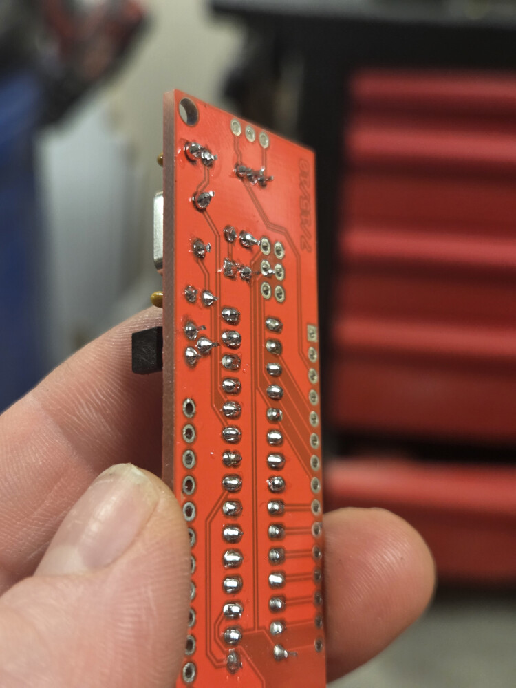
Most of them look good, I’d just add some flux and then add more solder to the pins that don’t have a ‘hershey’s kiss’ style mound (80-90% look fine) and re-test
Also: is the FTDI in 5v or 3.3v mode?
I only found out today I could switch modes on it when you mentioned it. I’ve not altered it since receiving it. It worked with the current LCD serial kit installed on our floor, so I would think it’s in the proper mode. Unless these new kits require 3.3v? Is there a way to determine that?
You can share a photo of its front and I can tell from that
I wonder if possibility a batch of 328s got put in these kits that don’t have a bootloader installed on them. That would explain why they work but can’t be reprogrammed.

The front doesn’t have any indicator of what mode it’s in, as far as the product page describes. The back would be where I’d install a jumper to switch modes:

Edit: to the earlier comment about resetting the board, the product page states “The DTR pin allows an Arduino target to auto-reset when a new Sketch is downloaded. This is a really nice feature to have and allows a sketch to be downloaded without having to hit the reset button. This board will auto reset any Arduino board that has the reset pin brought out to a 6-pin connector.”
I don’t understand the difference between working and being reprogrammed, in how you use them there. If they can’t be reprogrammed, doesn’t that mean they don’t work?
I had mis-remembered, the pads are on the back like you said…but anyhow, you have a 5v version and it should be outputting 5v (you can always test w/ a DMM to make sure it is in fact delivering the full 5v…let me know if it isn’t!)
Yea, if they don’t have a bootloader we’d need to send replacement units because they won’t interface as expected
Can you try a simple loop-back test with the FTDI by itself?
Apologies for all the run-around, but this is an odd duck!
I tried a loop back test with the FTDI by itself and it worked fine. Again, this same FTDI functioned properly when I tried uploading the code to the current board I’m trying to replace. It was just the newly soldered ones I’m getting this error on.
We happened to have yet another board lying around. Soldered that one up, was able to upload the code the first try without issue *shrugs* All I can say is that these two were duds somehow.
Working = they function as serial LCD’s and display the text you send them.
Reprogrammable = you are able to reload them with your own custom code.
Sparkfun flashes the program that makes these function as a serial enable LCD when they make the kit. There’s an important piece of code that goes along with the program that makes them function called a ‘bootloader.’
The bootloader’s job is to listen for a reset signal from the Arduino software when you request to load your new code onto the chip. When it sees a reset, the bootloader looks for a specific set of instructions getting the chip ready to receive a new program. Once it sees those instructions, it begins downloading your new code into the chip and then starts to execute that code.
It’s possible to flash the program to the chip but forget to flash the bootloader. If that happens, the chip will continue running whatever code is already on the chip but lacks a bootloader that allows you to upload new code to the chip.
In your case, it sounds like this may have happened. It’s fixable with the right tools and software but I think it may be more complex than your current abilities. (It can get pretty complex, especially if you’re a beginner.)
I’d hang on to the boards that won’t allow you to upload code, they should still function as serial LCDs just fine and be completely usable as LCDs. Later on when you have more skills and experience you might tackle adding a bootloader to them if you feel adventurous. ![]()
I ordered 2 more kits to be our back ups, and luckily I did, because the one I just got working on installed in the exhibit had its LCD screen blowout in 2 days.
However, I soldered up one of the brand new kits, tried to upload the same code with the same settings, same error message about the programmer not responding. I don’t see how I could get this many duds, if that’s the case, but no other solution makes sense.
Fwiw, when it’s plugged into my laptop, the TX and RX lights flash, and the TX blips on briefly during the upload attempts. I assume that means there’s some sort of communication going on, yet everything I’ve soldered together looks fine.
My colleague asked what temp I had been using for soldering, and I was at 435 F because that’s just what the gun was set to. Looks like the melting point is 361 F. I didn’t hold the tip there for any more time than necessary. That difference wouldn’t be enough to damage these boards, would it? Overall they don’t look to have any burn marks and the components don’t look like they’re bulging. He also thought I might be holding the soldering tip too long on the chip’s legs that it overloaded it, but I didn’t think I had it on there long enough to overheat it.
That shouldn’t be it, most of the solder joints look good temp-wise, though there are many that could benefit from added solder material (mainly about half of the non-main two rows…the central 2 rows look great except the last 2 on the serial-ended side)
We have an older guide with a bunch of tips & tricks How to Solder: Through-Hole Soldering - SparkFun Learn
This really looks like the classic communication breakdown issue. Since you’ve already checked the obvious stuff like cables, here are a few things that are easy to miss:
Sometimes the upload just misses the bootloader window. Try pressing and holding the Reset button, then release it right when the IDE switches from “Compiling Sketch” to “Uploading…”. That timing trick has saved me more than once.
If anything is connected to pins 0 (RX) or 1 (TX), disconnect it for now. Those pins are shared with the USB programmer, and even a small module can interfere with uploads.
It’s worth checking Device Manager (Windows) or System Report (macOS) to make sure the serial device is stable. If the port is dropping in and out, it could be a flaky CH340 or FTDI driver.
If it still doesn’t respond, sharing the exact board and OS usually helps narrow things down pretty quickly…
@Oliver2003 : you are posting AI-generated content, passing it off as your own experience. Please stop doing that. It is very misleading. In your posts, please state which AI engine you used so we can verify the content for ourselves. Thank you, Paul
The reset button was mentioned earlier in this thread. This board doesn’t have one.
The FTDI board is connected to the RX and TX pins in order to upload, as per the photos. What are you saying should be disconnected from those?
The port doesn’t drop in and out. It’s stable. I’ve already tried reinstalling the FTDI drivers, mentioned this earlier in the thread.
Yeah, this does seem ai generated content, instead of reviewing what steps I’ve outlined in this post.