I was wondering if the circuit I have attached is proper and will work as expected. I need to toggle a 12V valve on/off toggled by an Arduino that needs a least 6V. I have a 12V input to the MOSFET and then connecting the 3.3V output of that to a Buck Boost converter so that the Arduino gets at least 6V. Will the circuit below work?
Valve Control Diagram.pdf (646.2 KB)
Probably not. The valve coil requires an inductive kick bypass diode. If that is not present in the circuit, the MOSFET could be destroyed the first time it switches the solenoid.
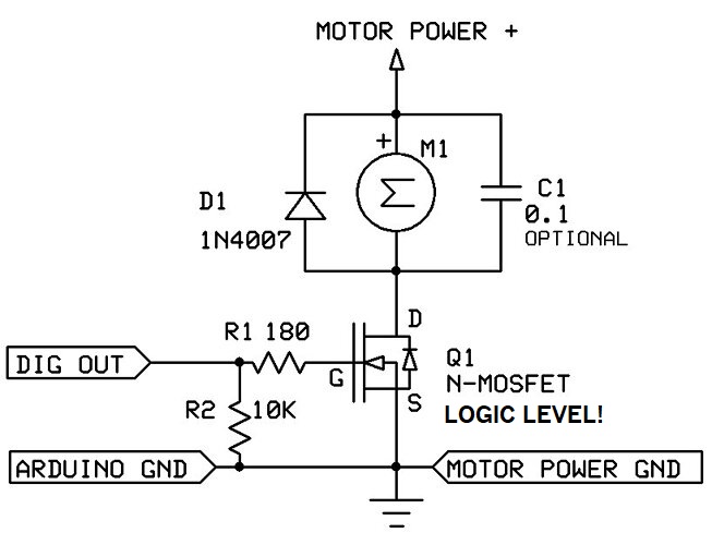
Example circuit for MCU control ( “M” is motor, valve coil, solenoid, etc., D1 is the inductive kick bypass):
What is an inductive kick bypass diode? Could I just add a diode in series with the valve signal? If not, what MOSFET and diode would you recommend?
Any diode that can handle the normal motor or valve current. It must be rated for the motor power supply voltage as well (reverse voltage). The 1N4007 is good for most low to medium voltage, low power motors, valves and solenoids.
Could I just add a diode in series with the valve signal?
No, it has to be wired across the valve terminals exactly as shown in the diagram.
Would this diode and this MOSFET be sufficient for a 12V signal?
With this configuration would it be possible to power the valve and an Arduino Giga w/ Display shield with the same 12V DC power jack input?
Yes, it would be possible.
What is the pinout of the MOSFET?
Would a 220 ohm resistor work instead of a 180? How does the MOSFET portion of the circuit work exactly?
Edit: a 220 ohm resistor works for this circuit