I have been a user of the Sparkx Qwiic Iridium 9603N in many devices and enjoy using it. It is no longer being sold, so I have decided to JLCPCB the boards and reflow my own version.
To that end, I am wondering if sparkfun would be willing to circulate the original BOM and firmware flashing protocol for it, so that users may continue on with the product… Or at least put eyes on a bom of my creation.
The SparkX GitHub Repo is still live and valid. The Eagle PCB files and firmware source code and binary are all on there. Eagle is still available - just - so you should be able to open those files and create a BOM yourself. If there are any parts you’re struggling with, let us know and we’ll give you the full part number. You can do that here, or open an Issue on GitHub. There is a BOM of sorts here that may help. It’s not completely up to date. We changed from press-in nuts to reflow standoffs on the final design.
Are you planning on asking JLCPCB to populate the board? Or are you thinking of populating them yourself - by hand? Just some friendly advice: the Samtec connector is really challenging to do by hand. It’s very easy to end up with shorts between the pins - which are actually blades. I’ve spent many hours reworking those on personal projects…
Many thanks for your reply - I wanted to wait until progress had been made to update you.
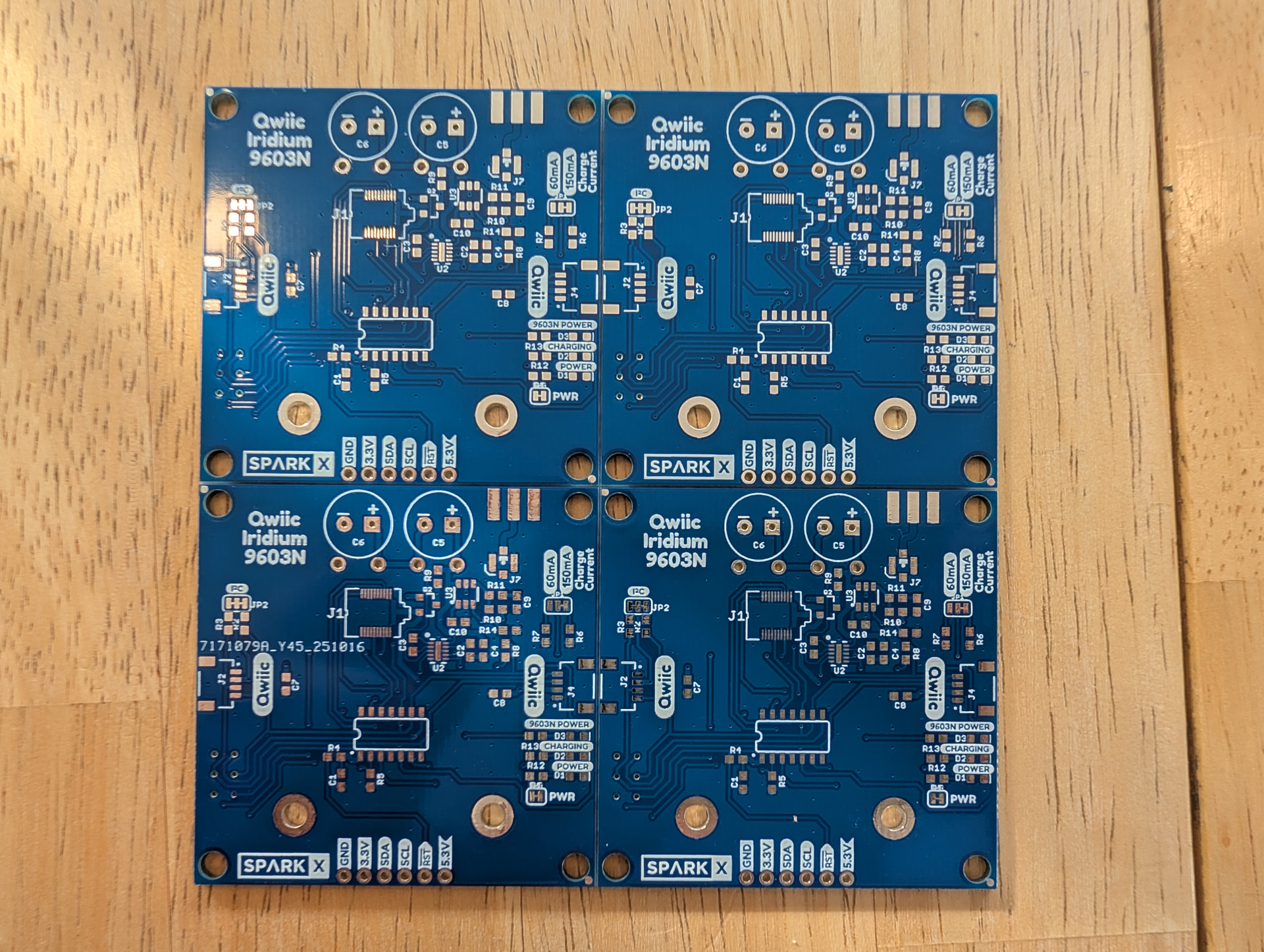
Un-populated boards have been produced (see photo). Using the sparkX repo, these were exported as gerber files from Eagle (only change was clicking ratsnest), then sent to JLC for fab/stencil production. I have a Controleo3 and paste ready for fab. I am aware that J1 is a bear and will report my outcomes - advice is welcome.
I have created an all-Digikey BOM from your “BOM of sorts”. This is my first BOM and I am unsure what the “gotchas” are, so if possible I would kindly request a BOM check (especially in the resistor section)… BOM can be found below (same file, in either Gdrive/digi link).
I’ve taken a quick look at your BOM and it seems OK.
The reflow standoffs we use are M2x0.4 x 6mm (DigiKey 732-7103-6-ND). They’re a lot easier to work with than the 2-56 press-in nuts.
Be careful when mounting the u.FL connector. If you put it on the wrong way round, it will have you scratching your head for days - trying to work out why you’re not getting an Iridium signal.
Because you’re assembling these by hand, you might want to use thermo-setting epoxy to hold the Samtec connector in position. Putting regular epoxy on after you’ve reflowed (and tested) the board is messy. Assembling by hand, you have the opportunity to put a couple of dots of thermo-setting epoxy on after you paste the board and before you place the connector. Chipquik AD1-10S looks ideal - but I’ve never used it.
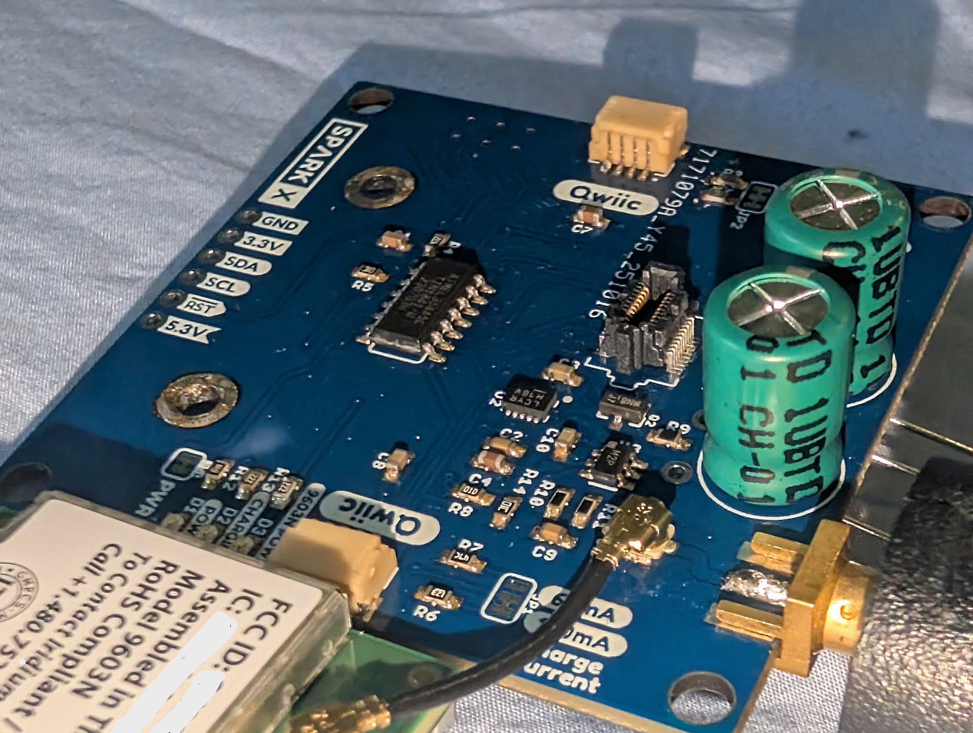
I am live on Rock7 and sending messages. Many thanks for your guidance, it gave me the confidence to get it done. See photo on Fig. 1.
Compact version: I have modified the PCB to be only a bit bigger than the modem itself (Fig. 2) for use in a pressure housing. ERC/DRC looks ok, but am not an EE so I would very much appreciate you giving any pointers… I’m sure there are details I don’t understand. Compact version brd/sch/grb files found at this github repo.
I am up and running with the mini version after adopting your recommended changes (see below). There was one quirk remaining after production, I had to scratch out the RST trace due to a poorly situated via which accidentally bridged to GND. Not sure why it wasn’t caught by ERC/DRC. I will update the design files in my github for the final version, which will be a little smaller still, and manufactured at 0.8 mm thickness. If folks are interested, we could refactor this in the featherwing form factor.
Many thanks for your support on this project, I have so appreciated the help.