Hello, our FTC team has been working with the SparkFun OTOS sensor, but we are consistently seeing incorrect distance readings.
What we’ve tried/our setup:
We have run both the unmodified sample OpMode and our own code (both show the same issue).
We use clean and flat FTC standard AndyMark tiles (new this year).
The sensor is mounted at the exact center of the robot, 10mm above the field tiles.
We have removed the Kapton tape, and the sensor lens is clean.
The testing environment is a consistent temperature.
We have tried adjusting the linear scalar.
We have adjusted the angular scalar (heading drift is now minimal, ~1e-11 °/sec).
Problem:
The OTOS consistently reports incorrect distance values.
The error isn’t uniform between X and Y.
From test to test the amount of inconsistency varies.
It increases as the robot moves, but not at a consistent rate (sometimes growing faster in X, sometimes in Y).
OTOS especially struggles when multiple waypoints are used Adjustment of the scalar
It’s not necessarily a growing error from one waypoint to another. It’s more of an error that may become larger or smaller from one waypoint to the next.
Questions:
Is there a way to adjust the X and Y scalars independently?
Has anyone else seen this issue on AndyMark FTC tiles, and if so how did you correct it?
Could this be a hardware issue, or is further calibration needed?
Any advice would be greatly appreciated — thank you!
Are you able to quantify how much error you’re seeing? The OTOS is rated for 1%, so if it’s within that amount, then it’s working as expected. If it’s significantly worse, then there’s a problem.
Also, could you please try repeating your tests on another surface, like concrete, wood, or paper? The FTC foam tiles are right at the edge of what the OTOS can track reliably, so if the behavior is different on another surface, that may give some clues of the root problem.
Is there a way to adjust the X and Y scalars independently?
No, they can only be changed together. This writeup gives some context for why they can’t be changed separately, because it’s not a simple adjustment along each axis, it depends upon the exact velocity in both axes. The linear scalar is a global scalar to the entire lookup table, there’s no way to tweak the lookup table without doing a lot of testing and uploading new firmware (which wouldn’t be legal for FTC anyways).
Thank you for getting back to us. We’ve conducted additional tests on FTC foam tiles and printer paper. For each run, the robot is told to go to 84" in the X or Y direction, while the other axis is held at 0". The main issue we observed during these tests is that the robot drifts by 5–6 inches in the axis that should remain at zero. We ran multiple trials (3–5 per direction, per surface), here are the results:
End = Final measurement reported by Sparkfun OTOS (inches)
Actual = Manual tape measure measurement (inches)
FTC Foam Tiles:
X-direction test (Avg)
End X: 84.67727…
End Y: -0.03454…
End H: -0.23346…
Actual X: 84.5625
Actual Y: -5.37168
X Error: 0.13572%
Y Error: 99.35700%
Y-direction test (Avg)
End X: 0.12975…
End Y: 84.74996…
End H: -1.44470…
Actual X: -4.935
Actual Y: 86.187
X Error: 102.62918%
Y Error: 1.66735%
White Printer Paper:
X-direction test (Avg)
End X: 84.70430…
End Y: -0.02803…
End H: -2.27239…
Actual X: 88.47916R66
Actual Y: -4.67166R66
X Error: 4.26639%
Y Error: 99.4%
Y-direction test (Avg)
End X: -0.13216…
End Y: 84.96462…
End H: -2.44263…
Actual X: -6.04166R66
Actual Y: 88.185
X Error: -97.81252%
Y Error: 3.65185%
* The end heading is irrelevant as the robot does not correct it during the tests.
* The % Error is calculated as: abs((abs(End - Actual) / Actual) * 100).
The error should not be calculated separately for each axis. The reason is because if one of your quantities happens to be zero, you’d get an infinite percentage, which is nonsensical. The error should be calculated as a single number.
Note that these assumes your robot drove in a straight line. If it drove in some kind of curve, then total_travel_distance would be longer.
Your tests show a consistent movement along the axis that should not be moving, which indicates to me that your sensor may not be mounted orthogonal to your robot’s chassis.
We can calculate the angle that it’s off by from each test as angle = atan(test_axis / non_test_axis):
FTC foam tile x-test: -3.6 degrees
FTC foam tile y-test: -3.3 degrees
White paper x-test: -3.0 degrees
White paper y-test: -3.9 degrees
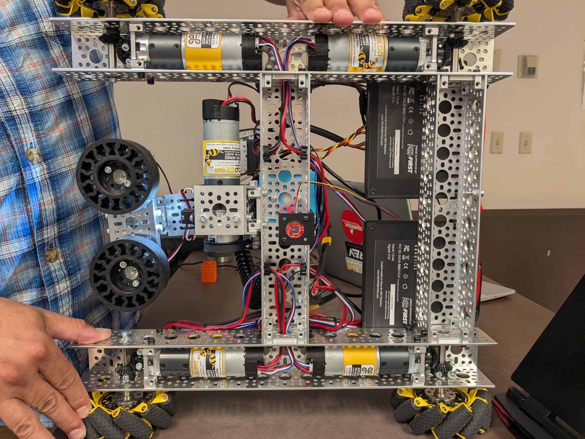
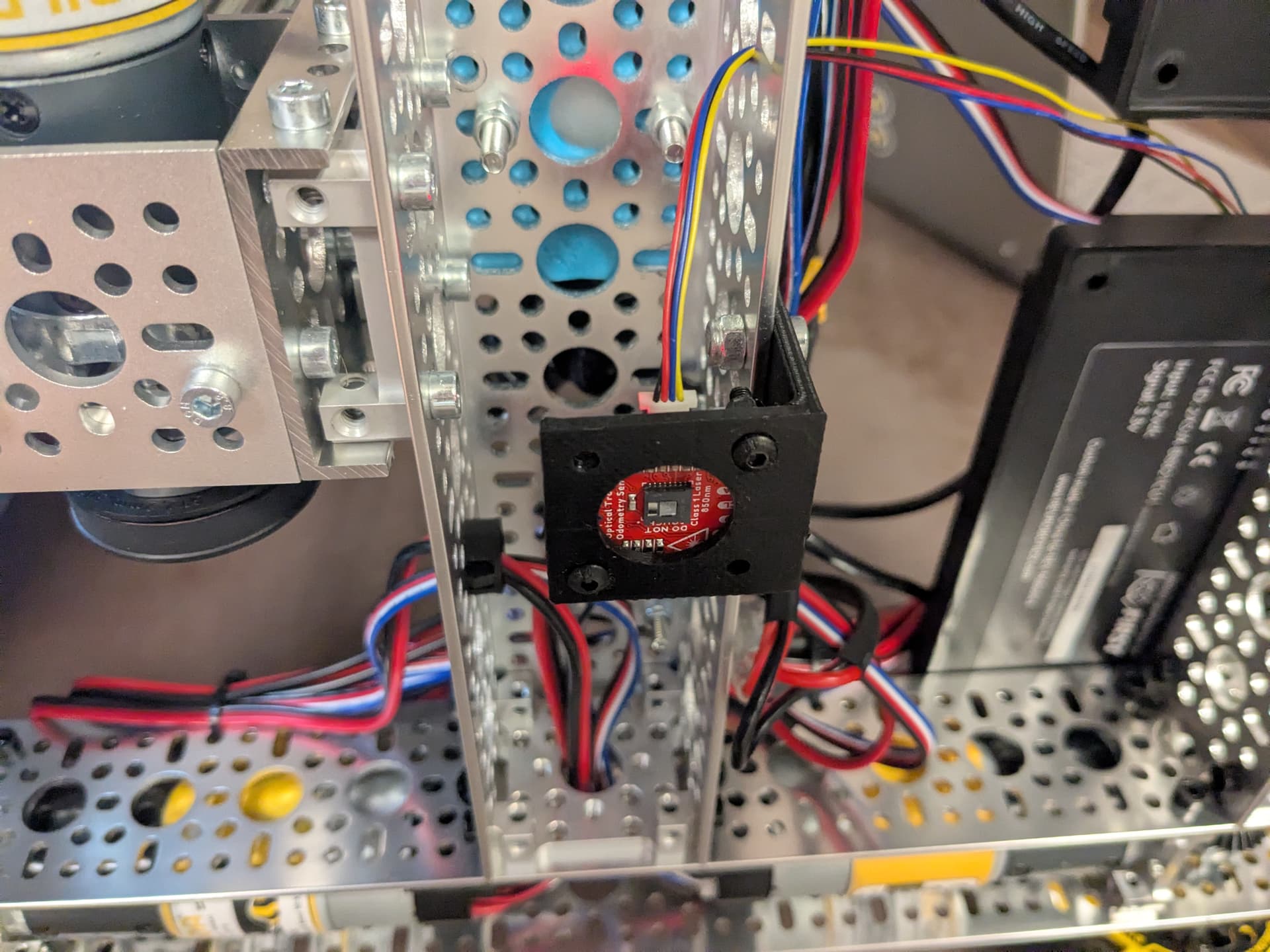
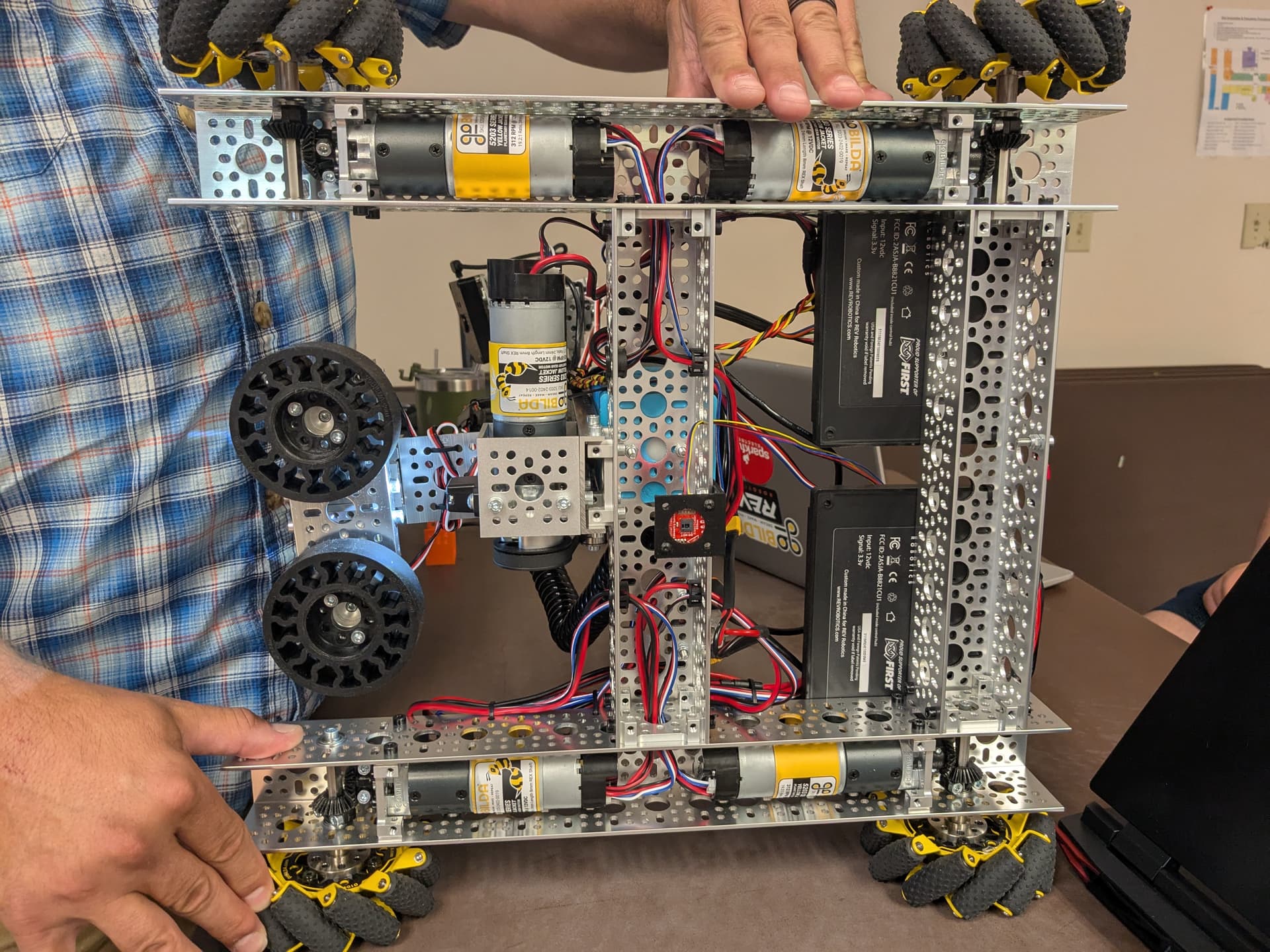
Could you please post an image showing how you’ve mounted the sensor? Is it noticeably off by a few degrees? Or is the optical chip itself off by a few degrees?
If so, I would suggest re-mounting the sensor to ensure it’s better aligned with your chassis.
If not, then you can try setting the offset angle in your code to something like 3.5 degrees to compensate for this. You’ll probably need to tweak your linear scalar after this since the error was consistently around 6 to 7 percent.
We also did some follow-up testing with the SparkFun OTOS, applying the offset angle and linear scalar adjustments you suggested. We found that an offset angle of: 0.4 degrees and a linear scalar of: 0.956 (with an angular scalar of: 0.9933) produced highly accurate results in both linear and strafing movement.
However, once the robot started moving diagonally, the SparkFun measurements quickly became inaccurate. In one test, the robot was given a sequence of predetermined coordinates to travel to, and by the time it reached the second position, the SparkFun readings were already significantly off.
At this point, would you recommend further troubleshooting, or should we consider moving toward getting a replacement?
Hmm, hard for me to tell from the images if it’s mis-aligned at all. Your mount seems like it may be a bit flexible, so when your robot drives around, it’s possible that the sensor is wobbling. Could you please try the mount linked below? It was created by the folks that manage the FTC Onshape parts library, and to my knowledge, teams have had a good experience with it.
We also did some follow-up testing with the SparkFun OTOS, applying the offset angle and linear scalar adjustments you suggested. We found that an offset angle of: 0.4 degrees and a linear scalar of: 0.956 (with an angular scalar of: 0.9933) produced highly accurate results in both linear and strafing movement.
Huh, 0.4 degrees is a lot lower than I would have expected to be needed, but glad to hear that it made an improvement!
However, once the robot started moving diagonally, the SparkFun measurements quickly became inaccurate. In one test, the robot was given a sequence of predetermined coordinates to travel to, and by the time it reached the second position, the SparkFun readings were already significantly off.
Numbers would be helpful for me to better understand how much error we’re talking about, everyone has different subjective ideas about what is “significant” and “accurate”.
I’d also like to know how you’re measuring the “actual” robot location. The data in your last post was down to 10 millionths of an inch, so I’m guessing you’re not using a tape measure. I would have guessed odometry pods, but I don’t see any in the images.
At this point, would you recommend further troubleshooting, or should we consider moving toward getting a replacement?
Only thing I’d recommend right now trying the mount I linked to ensure the sensor isn’t wobbling. Not sure if that would explain the error you’re seeing, but it’d probably be worth at least trying before getting a replacement.
Unfortunately, we weren’t able to get the mount printed in time. However, we did confirm that the sensor mount is very rigid, and we made sure it is not misaligned.
We used the term “accurate” to describe a <0.5 inch error. We also conducted additional tests and recorded the numbers below. Before running these tests, we repeated the linear trials (0, 100 & 100, 0) to confirm that the SparkFun OTOS remained consistent across sessions. Its performance was unchanged since our last session.
CX/CY = Final measurement reported by SparkFun OTOS (inches)
RX/RY = Manual tape measure measurement (inches)
Test Results: (Sorry for the bad table)
Diagonal (100, 100)
Offset Diagonal (90, 40)
Offset Diagonal, Mirrored (40, 90)
Seq, Point 1 (40, 90)
Seq, Point 2 (80, 110)
Seq, Point 3 (90, 40)
CX
100.780
90.712
40.502
40.141
80.439
90.231
CY
100.720
40.334
90.856
90.688
110.092
39.568
RX
101.10
88.25
41.05
40.65
80.15
91.70
RY
99.75
40.75
89.05
88.90
107.75
39.25
CX
100.167
90.820
40.550
40.550
80.775
90.279
CY
100.227
40.189
90.892
90.820
110.288
39.108
RX
100.15
88.50
40.85
40.95
79.95
90.90
RY
99.65
40.50
89.45
89.30
108.60
39.70
CX
100.540
90.664
40.322
40.394
80.391
90.375
CY
100.564
40.226
90.664
90.796
110.200
39.048
RX
100.50
88.40
40.95
41.10
79.70
92.00
RY
99.65
40.20
88.95
88.80
108.50
39.70
CX-Avg
100.496
90.732
40.458
40.362
80.535
90.295
CY-Avg
100.504
40.250
90.804
90.768
110.192
39.240
RX-Avg
100.583
88.383
40.950
40.900
79.933
91.533
RY-Avg
99.683
40.483
89.150
89.000
108.283
39.550
X-Diff
0.088
2.348
0.492
0.538
0.602
1.238
Y-Diff
0.820
0.234
1.654
1.768
1.908
0.310
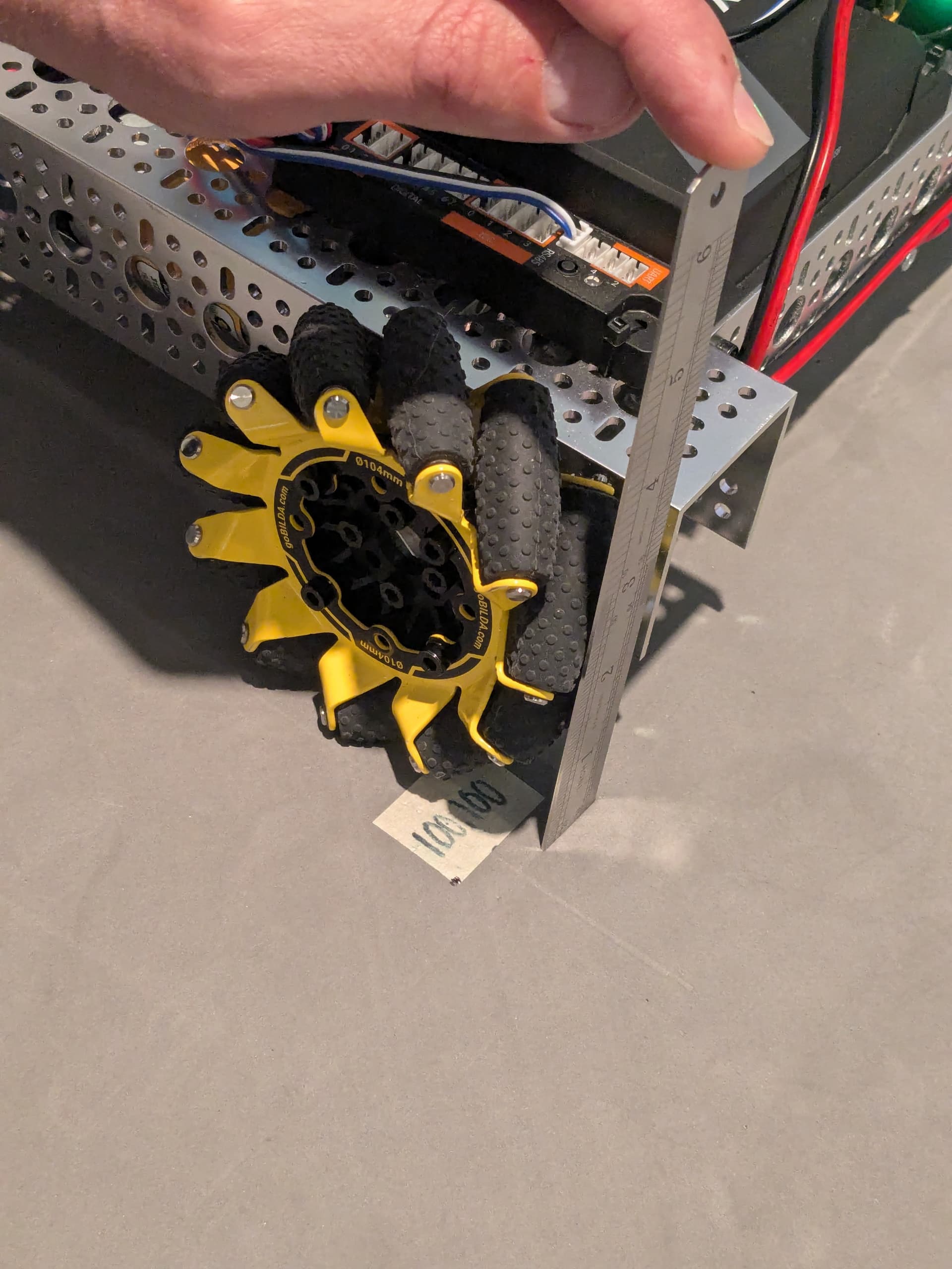
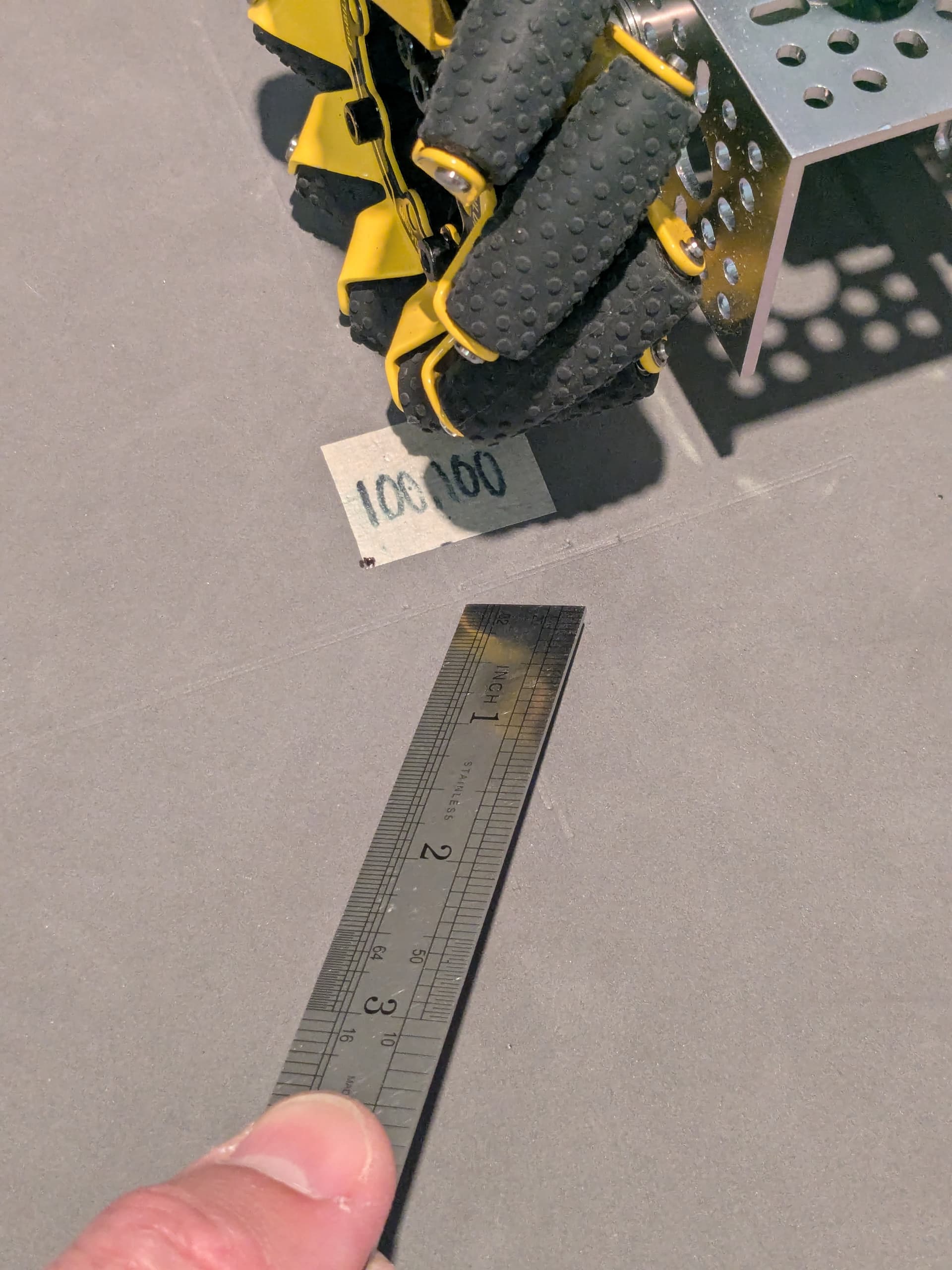
For our measurement method, we first mark the bottom-left wheel’s position by creating an imprint on the tile. We then measure the offset of the imprint from the tape corner (black dot), which had already been precisely measured.
Last session’s measurements came from measuring with a tape measure to 1/32 of an inch, then converting the measurement to a decimal. The excessive decimals (“10 millionths of an inch”) came from carrying too many decimals in our averages. This session’s measurements were taken precisely using a steel scale (a small metal ruler) with 1/10 inch graduations.
Follow-Up Question:
You mentioned odometry pods in relation to very accurate results. Would they be something worth considering? To your knowledge, are they generally more precise and/or reliable?
Gotcha. In that case, I’m not sure why you’re seeing such high error. It’s possible your specific unit has some manufacturing flaw, but I don’t have any further way to diagnose remotely.
Thanks for the clarification! Numbers are always appreciated.
Ah, good to know! Using a tape measure from the start location is good, just be careful about using too many decimal places, because it implies you have that many significant figures (also see accuracy vs precision, this was drilled into me in school ).
I’ll also caution about using a ruler; if you’re measuring from the teeth of the field tiles, be aware that FTC field tiles are slightly shorter than 24".
The implication in my previous message was that odometry pods can result in lots of decimal places, not that they’re accurate. If you were using odometry pods as your reference for the “actual” robot location, I would have asked that you go back and repeat with a tape measure, because odometry pods are not a ground-truth reference that can be fully trusted.
The accuracy of odometry pods can better or worse than the OTOS, depending on your implementation. If the pods are plugged into the Control Hub and you write your own odometry algorithm, that’s often worse than the OTOS because of higher and variable loop times (the Java garbage collector can create lag spikes that are 10s or 100s of milliseconds).
Not to tout our competitor’s product, but plugging odometry pods into the goBILDA Pinpoint Odometry Computer will be more accurate than the OTOS. It’s similar in function, except dead-wheels are inherently more accurate than optical measurements. So it’s more accurate, but the downsides are that it’s more expensive (as of writing, 2x pods at $75 each + 1x computer for $60 = $210 total, after goBILDA’s FTC discount), takes more space on your robot (2x pods + 1x Pinpoint versus 1x OTOS), and there’s more constraints on how you mount the pods (must be perfectly orthogonal).
If you’re after the most accurate localization, another thing you can do is utilize the AprilTags on the field with a USB camera on your robot. If you need help getting started, take a look at the ConceptAprilTagLocalization sample OpMode. Whenever a tag is visible, it will give the location of your robot on the field, which you can then use to update the OTOS (or Pinpoint) location.
Yet another option is to add touch sensors to the perimeter of your chassis, so when your robot bumps up against a wall or other known structure on the field, you can use that to reset one axis of your odometry implementation.
So, there’s a lot of options, each with their own advantages and disadvantages. Choose whatever makes the most sense for your team!