Stationary RTK without height with ZED-F9P receiver and ANN-MB-00-00 antenna

Am I performing a stationary RTK without height correctly with the ZED-F9P receiver and the ANN-MB-00-00 antenna? Does stationary mean static ?

I have configured the receiver in the u-center application:

  1. I have enabled only GPS and Galileo constellations for best accuracy
    GNSS (GNSS Config) → SBAS → Enable = empty
    BeiDou → Enable = empty
    QZSS → Enable = empty
    GLONASS → Enable = empty
    Send

  2. I set the measurement to stationary
    NAV5 (Navigation 5) → Dynamic Model = 2 - Stationary
    Fix Mode = 1 - 2D only
    Send

  3. I set the ZED-F9P to determine position for 3 seconds based on the last message from the base station. The base station sends messages 1/sec.
    NAV5 (Navigation 5) → DGNSS Timeout = 3
    Send

  4. I have enabled raw messaging for the USB port
    MSG(Messages) → Message = 02-15 RXM-RAWX
    USB → On
    Send

    MSG(Messages) → Message = 02-13 RXM-SFRBX
    USB → On
    Send

  5. I saved the configuration
    CFG(Configuration) → Save current configuration
    Send

My ZED-F9P receiver is a dual-frequency receiver L1/L2, so at my measurement location the sky should not be obscured by trees and buildings and should be at least 5 m from any terrain obstacles.

I placed the antenna with a metal round base connected to the ZED-F9P receiver on a round, level base on a tripod about 1.5m above the ground. The base’s task is to shield the antenna from below. Therefore, it should not be too large. The diameter of the base is a few centimeters larger than the diameter of the antenna. If it is too large, it will cause additional signal reflections and will be very susceptible to even small gusts of wind.

  1. The ZED-F9P receiver with 1.51 firmware is connected via USB to the laptop. The laptop has an Internet connection.

  2. I am launching the u-center application 25.03.

  3. I set the baud rate in the menu
    Receiver → Baudrate → 115’200

  4. I connect the application to the module in the menu
    Receiver → Connection → COMx

  5. I provide a window to display Fix mode by checking the selection in the menu
    View → Docking Windows → Data
    In the Data window, the Fix Mode field should display 2D.

  6. I enable receiving messages from the base station by selecting from the menu
    Receiver → NTRIP Client…
    Address:
    Port:
    Username:
    Password:
    NTRIP mount point:
    I click OK.
    If the connection to receive data from the base station was successful, the status at the bottom of the window will be NTRIP client: ip_address:port. The Fix mode field value in the Data window will change from 2D to 2D/DGNSS or 2D/DGNSS/Float. The base reference station is less than 10 km from the measurement site.

  7. In the menu I select View → Deviation Map to display a window with the measurement position.

  8. I click the button with the letter A at the bottom of the Deviation Map window meaning Set centre to average position.

  9. I wait until the Fix mode field in the Data window changes to 2D/DGNSS/Fixed. This may take a few minutes.

  10. When Fix mode is set to 2D/DGNSS/Fixed I click the Empty database button at the top to start collecting data from the beginning.

  11. I click the Properties button of the Deviation Map window located at the bottom, on the left side of this window. The Deviation Map Properties window will appear, in which the first field should be set to Average, and the Max. Deviation field should be set to 0.04. This is used to observe how large the spread of measurements is. If the measurements go outside the 2 cm circle, then we probably have low measurement quality. I click OK.

  12. I save the measurement results by selecting Player → Record in the menu. A window with a suggested file name will appear. I click save and confirm adding the receiver configuration by clicking Yes. Now the measurement results are saved to a file.

  13. I wait about 2 minutes, during which Fix mode should be 2D/DGNSS/Fixed all the time.

  14. I finish saving the results by selecting Player → Eject in the menu. I disconnect the NTRIP service by selecting Receiver → NTRIP Client… from the menu and disconnect the U-Center application from the receiver Receiver → Connection → Disconnect

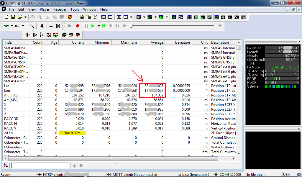
  15. I open the Player → Scan measurement file, select the file and click Open. I play the file to the end Player → Play → Maximum throughput and in the lower right corner of the Deviation Map window I read two numbers defining the average position. These are the 3D coordinates without height. Note: Not to be confused with the Longitude and Latitude fields of the Data window, which are usually located in the upper right corner.

  16. I disconnect the measurement file Player → Eject

Then using the Proj program, I transform the received 3D coordinates without height to the map system, i.e. the 2D system.

Fix Mode = 1 - 2D only forces a 2D fix (no height).
This will not allow a full 3D RTK fix, and height will either be undefined or projected to a 2D plane.

1 Like

It’s supposed to be a 2D fix. I’m asking does anyone do it the same way.

Yeah, I’m not convinced it’s doing the math any differently.

2D was more of a NMEA MARINE/BOAT thing, allowing for less satellites to be used in a solution to give the closest stab at a position in the least amount of time. Your depth in the ocean not being immediately critical in dispatching rescue craft, nor avoiding other vessels.

RTK, you’re looking at probably 8 satellites, with at least 5 from a single constellation, and it’s solving in 3D space, and arguably space-time.

I don’t think not-reporting height is a more winning strategy in terms of reporting 2D position than simply ignoring the height/altitude being reported.

1 Like

I’m not asking about the difference in calculation between 2D Fix and 3D Fix.

I would like someone to present a similar step-by-step guide on how to determine the RTK position for this receiver in order to share experiences. Everyone is sure they are doing everything right?

For many years I could not obtain reliable RTK results due to the poor quality of satellite systems. However, at the end of 2024 the situation changed, probably due to the expansion of the Galileo system.

However, I will respond to what you write:

If the calculations with 2D Fix are performed faster than 3D Fix, it means that a different algorithm is used, which may allow obtaining a solution in more difficult field conditions.
Although on the other hand I’ve seen so many tricks used by manufacturers that I wouldn’t be surprised if the 2D Fix was achieved by calculating the 3D Fix and not displaying the height.

Honestly, I would rather buy a receiver half the price and not containing mobile solutions for drones, cars, agricultural machinery and ships, loaded with interpolating algorithms when receiving data from satellites or base stations fails. I am only interested in static positioning.

The industry “lingo” generally uses Static to represent logging RAW data for post processing with long occupation times.

No, Not really…that I’m aware of.

I agree with @clive1. Constraining the solution to ~MSL way back during the Selective Availability (SA) days was beneficial for vessels. That’s not the case now.
I don’t see any reason for a 2D fix in the context of RTK. Of course, I could be wrong.

GNSS computation is trilateration at it’s core, expressed in ECEF.

The inherent GNSS solution is a 3D representation no matter what (as ECEF = X,Y,Z), even if you drop the “elevation” of the final Geodetic Coordinates at the very end.

As far at the workflow you described, I think your 21 steps could be much easier. But I don’t know the specific goals for your application.

You do get bonus points for a very detailed description :slight_smile:

3 Likes

Ok, but that’s not really how it works, even if you’re “stationary/static” or in “time mode”, everything else in the system is moving, the Planet rotates and the satellite wing along their arcs at orbital velocities.

The baseline is a 3D vector constraining the Rover to the established location of the Base. It is anchoring the reality and the commonality of the satellites in view.

I’m also NOT saying that 2D Fix is “faster”, just that it’s arrived at with less data/measurements and certainty. You can get there with 3 satellites, with 4 satellites you can more accurately determine time and location, and with 5 or more satellites you can look for and eliminate outliers. In older receivers the GPS signal acquisition was quite a task, and took time, these days it’s easier to throw thousands of gates, and dozens of channels, at the problem.

It’s also iterative, in the sense that you’re tracking the motion of the satellites wrt to the receiver, moving or not. Basically jostling spheres from trilateration

The Dynamics then play into how the receiver is moving wrt it’s prior location. ie whether it’s got velocity or acceleration, and how much is to be expected/tolerated.

1 Like

What ? Are you a poet ?

RTK measurement could be called online measurement and static measurement could be called offline measurement.

Do you mean RTK in 3D Fix Mode with default Portable model and receiver warm reset between measurements ? A cold reset when you start a new measurement session in a remote location.

When you are looking for a float solution, with or without differential corrections, it is mostly a least square method. If you have less parameters like fixed elevation, it should converge faster.

For the RTK fix, the least square is followed by an integer ambiguity resolution. This method is purely 3D. It is effective when the float solution is “in the range” of the true solution i.e. at a couple of wavelengths, a wavelength being 20 cm. So, if you start with a 2D convergence with a precise elevation evaluation (<20 cm), you way get a faster fix.

Static option in receivers is usually an optimization of Kalman parameters in the internal solution engine that should help getting faster convergence, booth for least square and RTK fix, if receiver is static.

But what is your initial problem? Trouble with getting fix?

1 Like

Imho this refers to a theodolite schenary only for azimuth values

no, only “trigonometria applicata alle stelle”
:+1: for Clive.

1 Like

I see that the answers are influenced by the tide resulting from the movement of the moon :upside_down_face:

Eric_S
Did I ask how the RTK position is calculated?
or
Is RTK with 2D Fix better than with 3D Fix?

Have you ever done these calculations or are you just repeating what you’ve heard?

This is a bit off topic, but I disagree:

Float solution is calculated for corrections.

When the receiver is stationary, the calculations are not performed faster but it can be assumed that there are no errors due to the motion of the receiver.

I’ve never noticed any difference in precision or convergence times between the dynamic models while testing the F9P.
Please Note: 10m/s is still an acceptable velocity for the Stationary Model.

I’ve watched my receivers maintain RTK fix while traveling at 80 mph many times… just for fun. The Satellites are moving 7 or 8,000+ mph. The motion of the Rover isn’t a major factor in the computation for RTK. RTK does not look forward or backwards in time (generally speaking).

On the subject of Warm & Cold Starts, your 21 steps make no mention of anything related to the Ephemeris and Almanac stored by the F9P (Warm vs Cold). You can delete those from the chip and force new data to be saved, but there is no purpose for that.

However, “Dumping” the antenna is a very useful tool while collecting data in the field.

More on my opinion on 2D vs 3D :
As I mentioned before, all GNSS measurements are performed via Trilateration from multiple satellites. This is without a doubt, a geometry problem in 3D.
We all know that elevation is the least accurate value of the X,Y,Z geodetic coordinate.
But the reason is purely Geometry. We are observing satellites from less than half the sphere (earth). If the RF signals could magically pass through the Earth (and without slowing down), then “X” would be the least accurate value in the geodetic position (we are spinning), instead of Z. Because we would be observing signals equally spaced around the sphere, instead of the strong overhead bias that we actually have :slight_smile:

In the Context of RTK, there are a lot of steps required to qualify the precision from any specific System (Base, Rover, Antennas, field technique, etc). Once that’s done, a single Epoch (1 second measurement) is a Good RTK Fixed Position Solution. I don’t see any benefit to attempt to “call” this solution a 2D position…because it’s not. Again, that’s just my opinion.

For RTK Workflow:
Averaging a few Epochs can help identify bad Epochs.
Dumping the Antenna is the next step.
Re-Observing the same point at a later time (different Environmental Conditions and Satellite Geometry) is the next step.

Qualifying the particular (and unique) System is the hard part, not the field work.

Side Note: Your F9P can outperform the ANN-MB-00-00 antenna you mentioned by a lot. That antenna is holding you back in your quest for GNSS precision.
Qualifying your correction source would be my next step.
“You can’t out-perform your antenna or your correction source.”

It’s worth noting that in the world of RTK, we can really only think in terms of precision at first (not accuracy). Accuracy starts at the Base Station.

If you require absolute accuracy and don’t control the particular Base, then Static Sessions (24 hour RINEX logs, multiple days, geodetic antenna) with PPP post processing is the answer. That position could then be used for a local base (temporary or permanent) if needed.

Many times, that’s not necessary. I have RTK Systems (from SparkFun) that I trust to 2cm precision with 1 second/Epoch shots. That’s usually ~1minute Time To First Fix at Startup. Then store 1 shot at any location as fast as I can walk around and plumb the rod. The correction source (and lots of testing/tweaking) are the major factors for trusting that. But I’ll still take another shot later in the mission on important POI’s for confirmation of elevation if needed.

Beh, rispondo di nuovo al caro professore ,nella lingua di Dante ,così da avere l’onere o il privilegio di essere frainteso nella traduzione…
I have reread all the six variants and I understood that Your intention is to have confirmation on the correct procedure;so I answer positively,but it would be lawful if you had a setup with a theodolite, which for simplicity of calculations consider only the plane coordinates. Using a gnss receiver, even the cheapest one, the situation is as seen by the Others…and, I think, that as for Cassini-Soldner also the Flat projection is deprecated for gnss.

Thank you for your reply as it is the first on the topic.

From what I understood you wrote that you do not measure position the same way as I do. You further explained why.

The main difference is that you don’t average the result from the point cloud like I do, you just read the measurement of one last point. I think it’s called instance measurement. This allows you to instantly read the result in the u-center app from the data window, which is usually located on the upper right side. You also do not need to clear the database or restart the receiver. You simply move to a new location and read the position. The same principle is probably used in all dynamic models where the antenna moves faster than the measurement frequency and the measurements with movement are called kinematic measurements.

I know the table you presented. Your comment that the selection of the dynamic model has no effect on the determination of the point position when the antenna is stationary or moving slowly indicates that the selection of the dynamic model is used to select an interpolation algorithm, i.e. one that calculates the approximate position in the case of rapid antenna movement and no data from satellites or a reference base station. This is very important when, for example, the car is driving in urban areas, so-called street canyons, because the receiver can constantly show the position, even if it is an approximate position. It is similar with agricultural machinery, where sometimes it is only important to maintain the direction of travel.

In a stationary measurement, I try to collect a point cloud with fix status over a period of several minutes and average it to determine the position. This allows me to achieve better accuracy by about 1 cm. Therefore it is important to clean the u-center database before measuring the next location. I do this in one of the steps. Can I use warm start instead?

I determine the horizontal position in the 3D coordinate system in which the coordinates of the base reference station were given. It is important to distinguish that I do not determine the position in the 2D coordinate system, only a 2D Fix is ​​determined, i.e. fix only for lon and lat. Then I convert lon and lat using the Proj program to the 2D coordinate system, i.e. the map system.

So I take measurements on different days to make sure I haven’t made a mistake or the satellite system works properly.

The ANN-MB-00-00 antenna with variations of the central phase point less than 0.01m is sufficient for me. The ZED-F9P RTK accuracy of 0.01m+1ppm, the distance from the base station less than 10km, gives the receiver accuracy of 0.01m+0.01m. I don’t remember now whether it is sufficient to sum it up. If so, it gives a theoretical accuracy for the antenna and receiver of 0.03m. However, averaging the point cloud allows for slightly better accuracy.

I sometimes perform static measurements using the rtklib demo package with a time of 50 minutes. It seems that the measurement time of 24 hours is exaggerated, because a few years ago I read a study that when measuring for several hours, the results obtained were not much different from 24 hours. The technology has advanced. It is important that the sky is not obscured and the antenna is at least 1 m above the ground.

OK. Thank you

Here’s an example of Single Epoch RTK points that I collected at random times over several days.
The Green Sphere is to represent the size of a Golf Ball for comparison.
This is the precision you can get from a properly configured RTK System.

As you can see in these results, averaging 2-3 minutes of data for each one of these positions wouldn’t provide any benefit to each individual data point. The main reason ( I believe ) is that at this level of performance, the main sources of error aren’t random. They are timing and environmental. Performing more measurements under different conditions is what makes me start to trust the position, not collecting more data under the same conditions.

We typically consider a 6 hour mission to be the minimum.
In the past, I have used 1 month of PPP data to establish the position for a CORS.
Is that overkill, ya probably. But the Base is logging RAW data anyway :slight_smile:
It’s easy to submit data 2 weeks later when final orbits are available to feel confident in the Base Coordinates.

It’s important to distinguish the difference in precision and accuracy.
In GNSS, 1 answer is a guess. 2 or more independent answers start to give you some insight on precision. Calculating accuracy is a whole different problem, because we rarely know the “truth” without a LOT of work, or accepting someone else’s work.

Also, please don’t think that I’m disagreeing with your comments. I’m just offering other opinions as I enjoy the discussions :zany_face:

I did another RTK measurement with the default 3D Fix and the default Portable model. It was a different location, but the point is the measurement method RTK for ZED-F9P with ANN-MB-00-00 antenna.

I have configured the receiver in the u-center application:

  1. I have enabled only GPS and Galileo constellations for best accuracy
    GNSS (GNSS Config) → SBAS → Enable = empty
    BeiDou → Enable = empty
    QZSS → Enable = empty
    GLONASS → Enable = empty
    Send

  2. I set the ZED-F9P to determine position for 3 seconds based on the last message from the base station. The base station sends messages 1/sec.
    NAV5 (Navigation 5) → DGNSS Timeout = 3
    Send

  3. I have enabled raw messaging for the USB port
    MSG(Messages) → Message = 02-15 RXM-RAWX
    USB → On
    Send

    MSG(Messages) → Message = 02-13 RXM-SFRBX
    USB → On
    Send

  4. I saved the configuration
    CFG(Configuration) → Save current configuration
    Send

My ZED-F9P receiver is a dual-frequency receiver L1/L2, so at my measurement location the sky should not be obscured by trees and buildings and should be at least 5 m from any terrain obstacles.

I placed the antenna with a metal round base connected to the ZED-F9P receiver on a round, level base on a tripod about 1.5m above the ground. The base’s task is to shield the antenna from below. Therefore, it should not be too large. The diameter of the base is a few centimeters larger than the diameter of the antenna. If it is too large, it will cause additional signal reflections and will be very susceptible to even small gusts of wind.

  1. The ZED-F9P receiver with 1.51 firmware is connected via USB to the laptop. The laptop has an Internet connection.

  2. I am launching the u-center application 25.03.

  3. I set the baud rate in the menu
    Receiver → Baudrate → 115’200

  4. I connect the application to the module in the menu
    Receiver → Connection → COM3

  5. I provide a window to display Fix mode by checking the selection in the menu
    View → Docking Windows → Data
    In the Data window, the Fix Mode field should display 3D.

  6. I enable receiving messages from the base station by selecting from the menu
    Receiver → NTRIP Client…
    Address:
    Port:
    Username:
    Password:
    NTRIP mount point:
    I click OK.
    If the connection to receive data from the base station was successful, the status at the bottom of the window will be NTRIP client: ip_address:port. The Fix mode field value in the Data window will change from 3D to 3D/DGNSS or 3D/DGNSS/Float. The base reference station is less than 10 km from the measurement site.

  7. In the menu I select
    View → Deviation Map
    to display a window with the measurement position.

  8. I click the button with the letter A at the bottom of the Deviation Map window meaning Set centre to average position.

  9. I wait until the Fix mode field in the Data window changes to 3D/DGNSS/Fixed. This may take a few seconds.

  10. When Fix mode is set to 3D/DGNSS/Fixed I click the Empty database button at the top to start collecting data from the beginning.

  11. I click the Properties button of the Deviation Map window located at the bottom, on the left side of this window. The Deviation Map Properties window will appear, in which the first field should be set to Average, and the Max. Deviation field should be set to 0.04. This is used to observe how large the spread of measurements is. If the measurements go outside the 2 cm circle, then we probably have low measurement quality. I click OK.

  12. I wait about 2 minutes, during which Fix mode should be 3D/DGNSS/Fixed all the time.

  1. In the menu I select
    View → Statistics View
    to display a table with the average measurement position.