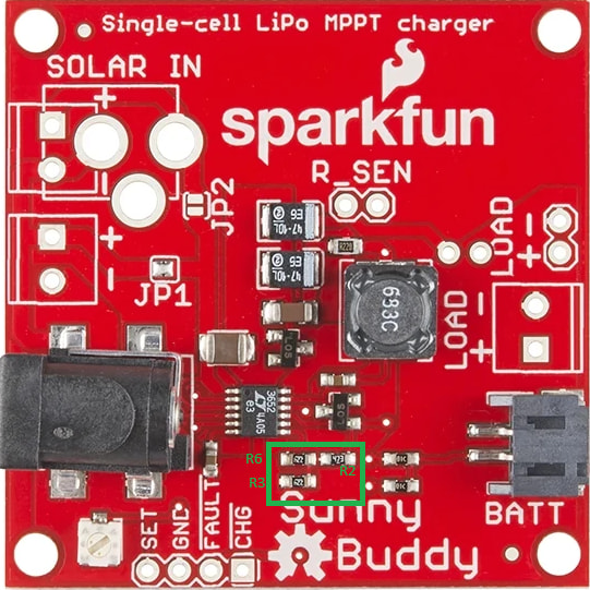
In my lab I have a bunch of old sunny buddies that a previous manager modified to charge to 7.1 volts. No documentation was made about how this was done. I need to modify a new batch of sunny buddies for my students that also charge to 7.1 V because the students break them and wear them out over time. I read all the documentation on the sparkfun website (datasheet and schematic and hookup guide) and it is shown how to calculate which resistors are needed, but there is no picture that unambiguously relates the schematic or datasheet to the actual, physical board.
In short, I need to know which three resistors on the actual sunny buddy are the ones discussed in the datasheet for adjusting float voltage. I can make a pretty good guess, but the traces are hard to see and the resistors are not labeled and I am not absolutely sure. If sparkfun could produce a picture labeling the resistors in question, that would make this pretty simple.
Thanks very much,
Justin