Hello,
I am trying to wire up a few Gesture Sensors (APDS9960) to an Arduino Uno using a Multiplexer (74HC4051). However I am not sure how to wire up the SCL and SDA lines of the APDS9960 to the Mux. Any help would be welcome.
Hello,
I am trying to wire up a few Gesture Sensors (APDS9960) to an Arduino Uno using a Multiplexer (74HC4051). However I am not sure how to wire up the SCL and SDA lines of the APDS9960 to the Mux. Any help would be welcome.
The best way would be to use an I2C mux (like BOB-14685) , according to https://forum.arduino.cc/index.php?topic=401223.0 the 74HC4051 would work. They recommend running SCL to all I2C devices in parallel (with one pullup) and use the mux for SDA (with a separate pullup on the host side and on each slave side). Try 10k or 4.7k as the pullups.
/mike
Thank you. I’ll take a look at the arduino forum and give it a shot. For further clarification, would anything need to be connected to the “Z” pin of the mux?
The Arduino would connect to Z; the sensors to Y0…Y7
Hi, I tried it out and it works great for just reading data. Thank you!
I then tried using the proximity detection mode with 2 different sensors wired into 2 different interrupt pins, but one of the devices doesn’t initialize when it is in this state.
Could this be a HW or SW issue?
Hi kspark!
Probably the easiest way to do what you’re looking to do would be to use a mux that’s specifically designed for use with I2C. The product n1ist recommended ([BOB-14685) would be ideal and is itself a I2C device that you can select the channel you want active via I2C.
However, you can use a non I2C mux, but you will need a few extra I/O pins on your microcontroller to select what channel you want.
The part you’re using, ([BOB-13906) will work but it only allows you to switch one line to 8 devices and I2C uses 2 lines. (SDA and SCL)
Fortunately, all your devices can share the same clock so you don’t need to switch the SCL line. Connecting all the SCL lines together and switching the SDA line to whatever device you want to talk to would work.
You can think of the 74HC4051 as a single pole, 8 position rotary switch where Z is the terminal connected to the knob, and the Y0 to Y7 terminals get connected to Z as you turn the knob. If it were a hand operated switch, it would look like this:

The picture below shows a simplified view of what the 74HC5041 looks like inside.
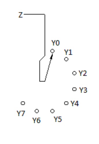
A regular rotary switch would have a knob on it you turned with your hand but the 74HC4051 uses three terminals labeled S0, S1 and S2 to select what position to turn the switch too. By pulling those three pins high or low in the right combination, you can move the switch to any of 8 possible positions. Think of those three pins as binary inputs. If you want to select Y0, a binary zero on those pins (0,0,0) will select Y0. Sending a binary 7 (1,1,1) will select Y7.
The picture below only shows three I2C devices to make the drawing easier to understand, but will work for up to 8 devices. Give that a try and you should be OK. You will need to write your code to switch channels by toggling S0, S1 and S2 high or low but once you’ve done that, the rest of your code is free to talk to the device on the selected channel.

I then tried using the proximity detection mode with 2 different sensors wired into 2 different interrupt pins, but one of the devices doesn’t initialize when it is in this state.
Could this be a HW or SW issue?
That’s likely an issue in your code. Unfortunately we can’t help with your code, but you will probably need to have the code figure out what sensor triggered the interrupt and then switch to that sensor before attempting to read the sensor. My guess is your code isn’t switching to the sensor that triggered the interrupt and is trying to read the wrong sensor.
Hope this helps!](SparkFun Multiplexer Breakout - 8 Channel (74HC4051) - BOB-13906 - SparkFun Electronics)](https://www.sparkfun.com/products/14685)
Hi Chris,
Thank you very much for the detailed explanation!
I will review everything again and hopefully get it to work!