since years we are successfully working with your products, mostly Thing Plus MCU boards and also GPS with ZED-F9R.
with that setup in the end we are mostly able to work how we need (SPI interface between the two and also a third Dual-port shield parallel on SPI).
In last months we wanted to start use also the other variant of ZED-F9P.
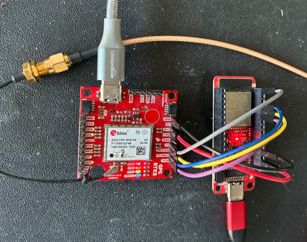
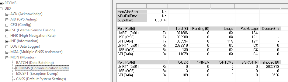
so ordered two board (GPS-16481) and after a brief setup already stumble in SPI problems:
I soldered the DSEL jumper and connected all the SPI lines, also update all the ZED-F9P firmware via U-Center.
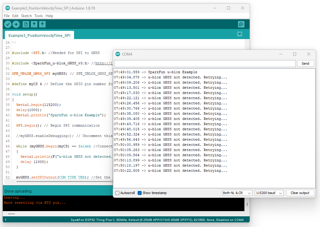
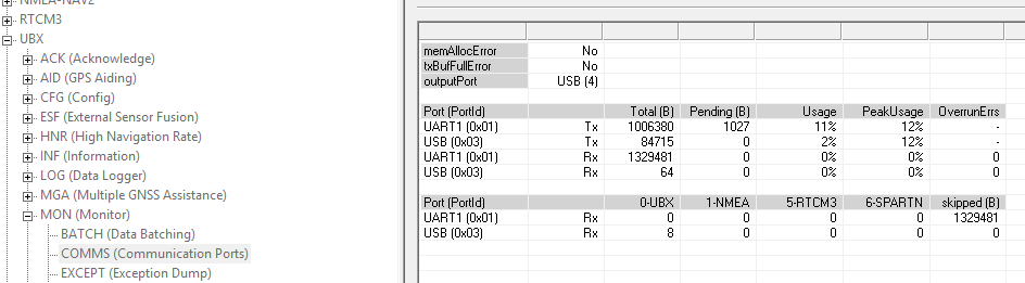
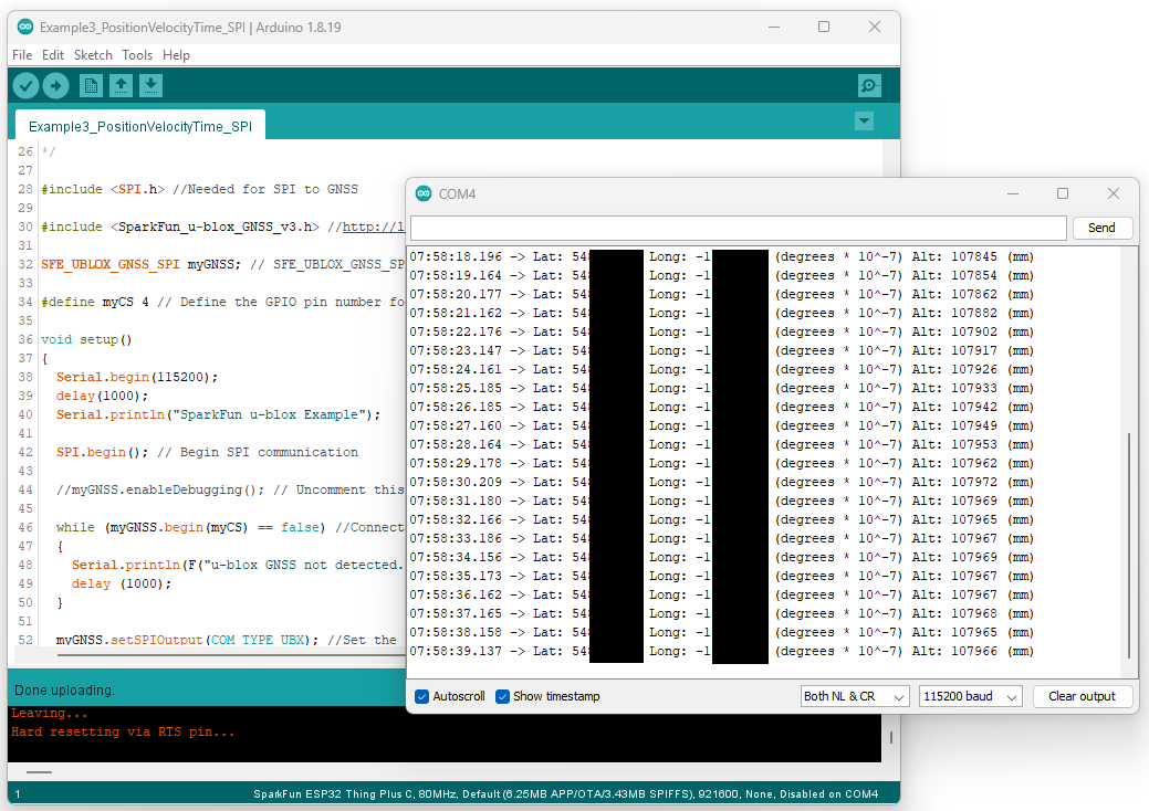
anyway in the end only one of the two works via SPI, the second doesnāt (maybe few time did..) but via I2C works fine.
Also checking in the forum find out that this was an issue (not sure if from Ublox or from your boards).
in the end thought that maybe just one of the two board was defective and so order two more (this time without SMA, GPS-15136).
unfortunately yet both of the two are showing the same SPI limitations, almost no one works as it should (also after firmware update and DSEL soldered..).
Now I want to know directly from you if youāre aware of these problems, if you already had debug it, if you maybe have made another labeling mistake on the board silkscreen or layout for SPI pins (like for the ZED-F9R, GPS-22660 or GPS-22693)
without only addressing it in the forum and not correcting on the product
(not so professional, it cost me 2 x PCB design by the way).
Anyway before starting some claim or warranty procedure, hope you maybe can better address this point.
I have noticed that the ZED-F9P can be reluctant to start in SPI Mode if it has previously been used for UART and/or I2C. I added some notes about this in the post you linked. Please connect via USB and try setting the Protocol In and Protocol Out using u-center and UBX-CFG-PRT: set UART1 and I2C to None; set SPI to UBX+NMEA+RTCM3. Ensure the configuration is saved to both Battery-Backed RAM and Flash using UBX-CFG-CFG. Then restart. That should get the SPI interface working.
The SPI pin labelling error was limited to the ZED-F9R board. The ZED-F9P boards are labelled correctly.
We have used SPI very successfully in the RTK Reference Station. The interface between the ESP32 and the GNSS is exclusively SPI.
Hi,
thanks for the prompt reply.
anyway tried again with your suggestion but only solved the problem partially:
here the simple code we are using to debug. we use an SPI connection of 4 MHz and also tried lower (e.g. 1 MHz) but having the same issue)
ZED-F9P firmware v 1.51
#include <SPI.h>
#include <SparkFun_u-blox_GNSS_v3.h> //http://librarymanager/All#SparkFun_u-blox_GNSS_v3
SFE_UBLOX_GNSS_SPI myGNSS;
#define spiPort SPI
#define CS_SD A5 // SD A5
#define CS_GPS 6 // GPS
void setup() {
Serial.begin(115200);
// set the CS of GPS/SD card SPI to high (to force it in case of a reset)
pinMode(CS_GPS, OUTPUT);
digitalWrite(CS_GPS, HIGH);
Serial.println("start test");
spiPort.begin();
delay(50);
// Do a fake transaction to initialize the SPI pins
spiPort.beginTransaction(SPISettings(4000000, MSBFIRST, SPI_MODE0));
spiPort.transfer(0xff);
spiPort.endTransaction();
Serial.println("Fake SPI success");
delay(50);
bool begun = false;
do {
Serial.println("SPI begin");
begun = myGNSS.begin(spiPort, CS_GPS, 4000000);
//Serial.println("SPI loop");
if (!begun) {
Serial.println(F("u-blox GNSS not detected on SPI bus."));
delay(1000);
}
} while (!begun);
delay(50);
Serial.println("Waiting for ZED F9P to connect over SPI");
myGNSS.setAutoPVT(true); //Tell the GNSS to "send" each solution
}
actually we have three board ZED-F9P:
2 x GPS-15136 (No. 1, 2),
1 x GPS-16481 (No. 3)
in attachment the type of results we are getting
unfortunately only sometimes they communicate and also then most are errors.
i still believe this Board (HW) or the SW (Library) arenāt properly working, for sure not well like the ZED-F9R model used before (only with 1x ZED-F9P about 4 (1xGPS-16481 is the only one which seems to work reliably..)
Do you think there are other better way to use it via SPI? I2C is maybe limited for what we need.
Currently on this status we cannot use the Boards as wished.
This is strange⦠As I mentioned we use SPI in the RTK Reference Station, and the firmware uses the same SparkFun_u-blox_GNSS_v3 library to handle the communication. That product works very well.
Please tell me more about your hardware setup. Which processor / microcontroller board are you using? How do you have the two boards connected? Please share a photo showing the connections between the boards if you can.
You havenāt shared all of your code. Please also share the loop with the call to getModuleInfo.
Also, I see #define CS_SD A5 // SD A5 in your code. That suggests you also have an SD card connected. Is it sharing the same SPI bus? You do not initialize the CS_SD pin. Please try adding:
If possible, please share the schematic and gerbers for your carrier board, so we can check the SPI connections. If you canāt share, please check you have all the POCI=CIPO=MISO signals connected together; and all the PICO=COPI=MOSI signals.
For SPI, you need to make sure that each device on the bus is powered and has its chip select pin pulled high. If a device is off, or its chip select is left to float, or - worse - the chip select is low, you will get data corruption. Communication may be impossible.
Please check that you are pulling the correct pin high for the SD chip select. On the ESP32 S2, āA5ā is GPIO 5. Is that correct? If you share your schematic and gerbers, we can check.
Also, do be careful with your SPI modes. We have talked previously about SPI modes here.
schematics is very simple:
just the Thing Plus ESP32-S2 connected to the other two boards, besides 3V3 and GND also I2C (needed for SD first change to SPI..) and SPI.
also some led on IO11 and IO12 and a button on IO10.
as said this works fine with the ZED-F9R but very bad or almost never with the F9P.
how you see in the code the CS_GPS is IO06 and CS_SD is A5 (you are correct is IO05). Print ESP32-S2_Thing_Plus.svg
about the SPI lines, how said I only had problem because of the wrong label of the ZED-F9R, but then always connected from ESP32-S2 to GPS
COPI to MOSI
CIPO to MISO
SCK to SCK
but then if the connection are wrong how could we sometimes read anything via SPI?
Honestly Iām more curious to know if you tried multiple times, with different ZED-F9P, youāre SPI test setup and it always worked fine at first. As said by us yet only 1 of 4 are working properly.. maybe you had some batch not properly soldered.
about other mappable HW interface, I know there must be other two (SPI2 and SPI3) available, will maybe check them later, but why arenāt the default working?
Well there are a lot of settings and undocumented keys, so if you have a configuration file you can kitchen sink a whole lot of unhelpful settings into FLASH configuration space. Can make things very sticky. And there are option settings that can also force behavior independently of the pins, like remapping interfaces or disabling.
DSEL has worked for me on factory parts without issue.
not completely clear on the last Flash configuration part: I personally never modified the one on the ZED-F9P.
then if I first do a firmware update and then set the interface variable in u-center (like asked here for the interfaces) which other flash settings should be wrong? shouldnāt the board/chip work out of the box?
why it is so different (difficult) from the ZED-F9R anyway?
From the beginning I also thought that the problem is more on the U-blox part, but if you all say that your ZED-F9P work with SPI out of the box then is not the case
If you do a firmware update with Chip Erase it should clear settings there.
Otherwise things can be retained there or BBR.
Iām saying that you might have difficulties if you use a Configuration file via uCenter Classic, which can push in a lot of settings that you donāt want and canāt see. This is a situation Paul alludes too. There are methods to suppress DSEL, but I doubt youāve engaged those.
UARTs tend to be preferable, as they are a more natural why to output data from the receiver without host interaction. Most ESP32 and SAMD devices have several UARTs
Iām sorry. I donāt understand why youāre having so many problems. If your ESP32S2 works with the ZED-F9R, then it should work equally well with the ZED-F9P. The SPI interface is exactly the same.
To fully understand what is going wrong, you may need to put a logic analyzer on the SPI bus and look at the signals on all four lines.
Just to be clear, the SPI pin order is the same on both the ZED-F9P and ZED-F9R boards. Looking at your photo and going from ātopā to ābottomā, the ZED-F9P pins are
CS
RX/MOSI
TX/MISO
SCK
The pin order on the ZED-F9R is the same:
CS
The silk says RX/POCI, but the signal is actually RX/PICO
The silk says TX/PICO, but the signal is actually TX/POCI
SCK
With your orange/yellow/green/blue wires, whatever order works for the ZED-F9R, the same order should work with the ZED-F9P. You should not need to swap the PICO/POCI wires between the two versions.
The SPI interface works very well on the RTK Reference Station. That is able to log RAWX and SFRBX at the full 20Hz.
then about the SPI connection, how said normally it works fine with every other ZED-F9R used (many), is just that mostly with ZED-F9P isnāt (many).
Iām most curious to know from you or someone else if the Sparkfun RTK (ZED-F9P) board works always (not just one board..) via SPI or there are others with this same problem