Help needed for Tilt Compensation setup using GNSS Flex pHAT ZED-X20P & IM19

Here’s what I have so far:

  • GNSS Flex pHAT ZED-X20P on Raspberry Pi 5 running NTRIP Caster to my LAN over wifi
  • GNSS Flex pHAT ZED-X20P & IM19 EMU on Raspberry Pi 5 running NTRIP Client connected by wifi
  • Using PyGPSClient for configuration, monitoring, testing, etc.

The base is mounted in a fixed position in my yard and the rover is currently mounted on a tripod. I have reliable RTK FIXED positioning. I have also been successful using SW Maps over Bluetooth.

I am trying to set up Tilt Compensation, but have had no success so far.

I enabled four UART devices on by Pi according to Software Overview - SparkFun GNSS Flex System Hookup Guide , but I don’t know why I need four…

Why four?

I am using the PyGPSClient UBX Configuration to set UART baud rates to 460800, and Preset UBX Configuration Commands to Enable NMEA High Precision. I also set the CFG_MSGOUT_NMEA_ID_GST_UART1 to 1, and checked that GGA and RMC messages are set to the default 1 values.

I also used the recently added TTY Preset for “Feyman IM19 Tilt Survey Setup”.

I enabled the EMU Monitor View in PyGPSClient to see if I was getting in data. So far, I have seen none. I went out to the rover, picked it up, and tried shaking to initiate the unit, but that did not have any effect. There is no audible feedback as described in this video: What Is Tilt Compensation? - News - SparkFun Electronics

How can I know when the IM19 has been activated and calibrated?

Any tips for getting this working?

Hi Steve (@steve.talent ),

I almost added in my previous post “let us know when you need a hand configuring the IM19”! Here we are…

Ideally, we need a tutorial showing you how to do this - with PyGPSClient. @semuadmin has already provided a lot of information, but you will need more help working out the IMU coordinate system.

I have some very rough notes that I wrote while I was testing the X20P + IM19 on PyGPSClient. But they are rough and not really fit for public consumption. I will send you a link to those privately, just to get you going in the right direction. The public tutorial will follow in due course.

More later,
Paul

2 Likes

Here are more notes on configuring the X20P and IM19 on the pHAT using PyGPSClient:

The SparkPNT GNSS Flex Module - ZED-X20P & IM19 IMU combines the X20P and IM19. Using Flex UART numbering:

  • UART1 is ZED-X20P UART1 (Defaults to 38400 baud)
  • UART2 is ZED-X20P UART2 (Defaults to 38400 baud)
  • UART3 is IM19 UART1 (Defaults to 115200 baud)
  • UART4 is IM19 UART2 TX (Defaults to 115200)

On Raspberry Pi 5, these correspond to:

  • UART0 (GPIO 15 and 14)
  • UART3 (GPIO 9 and 8)
  • UART2 (GPIO 5 and 4)
  • UART4 (GPIO 13 and 12)

On Raspberry Pi 4, the numbering is different: UART0, UART4, UART3, UART5.

The default jumper settings on the Flex module connect X20P UART1 TX to IM19 UART2 RX:

image

The IM19 needs NMEA GPGGA, GPRMC and GPGST at 5Hz. So we need to configure the X20P UART1 to provide these, at the correct baud rate.

The IM19 also needs a 1Hz Pulse-Per-Second. On the Flex module, the X20P TIMEPULSE is connected directly to IM19 1PPS.

Side note: The jumpers can be modified to route X20P UART2 TX to IM19 UART2 RX; or Flex UART4 RX to IM19 UART2 RX.

Side note: An early prototype of the Flex X20P IM19 Module had a slide switch, making it easier to route X20P UART2 TX to IM19 UART2 RX. We later reserved Flex UART2 for “Radio” RTCM corrections, which is why the jumpers route X20P UART1 TX to IM19 UART2 RX.

The X20P is configured using the “Configuration Interface” (UBX-CFG-VALSET and -VALGET). The older UBX-CFG-MSG and UBX-CFG-PRT messages are deprecated and no longer supported.

To configure the X20P we need to first change the UART1 baud rate:

CFG_UART1 CFG_UART1_BAUDRATE 115200

On PyGPSClient, you will need to close the port and re-open at 115200 baud after applying this setting.

Then:

CFG_UART1OUTPROT CFG_UART1OUTPROT_NMEA 1
CFG_MSGOUT_NMEA CFG_MSGOUT_NMEA_ID_GGA_UART1 1
CFG_MSGOUT_NMEA CFG_MSGOUT_NMEA_ID_GLL_UART1 0
CFG_MSGOUT_NMEA CFG_MSGOUT_NMEA_ID_GSA_UART1 0
CFG_MSGOUT_NMEA CFG_MSGOUT_NMEA_ID_GST_UART1 1
CFG_MSGOUT_NMEA CFG_MSGOUT_NMEA_ID_GSV_UART1 0
CFG_MSGOUT_NMEA CFG_MSGOUT_NMEA_ID_RMC_UART1 1
CFG_MSGOUT_NMEA CFG_MSGOUT_NMEA_ID_VTG_UART1 0
CFG_NMEA CFG_NMEA_HIGHPREC 1
CFG_RATE CFG_RATE_MEAS 200

In PyGPSClient Preset JSON format, this will be:

"ubxpresets_l": [
  "Set UART1 to 115200 baud, CFG, CFG-VALSET, 000700000100524000C20100, 1",
  "Set IM19 NMEA on UART1, CFG, CFG-VALSET, 000700000200741001BB00912001CA00912000C000912000D400912001C500912000AC00912001B100912000060093100101002130C800, 1"
  ],

IM19 configuration will follow…

1 Like

To configure the IM19, it is easiest to open a second instance of PyGPSClient and connect to Pi UART2 (usually /dev/ttyAMA2) at 115200 baud.

We need to configure the IM19 using “AT” commands. PyGPSClient calls these “TTY” commands:

AT+LOAD_DEFAULT
AT+GNSS_PORT=PHYSICAL_UART2
AT+NASC_OUTPUT=UART1,ON
AT+LEVER_ARM2=0.0057,-0.0732,-0.0645
AT+CLUB_VECTOR=0,0,1.865
AT+INSTALL_ANGLE=0,180,0
AT+GNSS_CARD=OEM
AT+WORK_MODE=408
AT+CORRECT_HOLDER=ENABLE
AT+SET_PPS_EDGE=RISING
AT+AHRS=ENABLE
AT+MAG_AUTO_SAVE=ENABLE
AT+SAVE_ALL

In PyGPSClient Preset JSON format, this is:

    "ttypresets_l": [
        "INIT_PRESETS",
        "IM19 Tilt Survey Setup; AT+LOAD_DEFAULT; AT+GNSS_PORT=PHYSICAL_UART2; AT+NASC_OUTPUT=UART1,ON; AT+LEVER_ARM2=0.0057,-0.0732,-0.0645; AT+CLUB_VECTOR=0,0,1.865; AT+INSTALL_ANGLE=0,180,0; AT+GNSS_CARD=OEM; AT+WORK_MODE=408; AT+CORRECT_HOLDER=ENABLE; AT+SET_PPS_EDGE=RISING; AT+AHRS=ENABLE; AT+MAG_AUTO_SAVE=ENABLE; AT+SAVE_ALL",
        "IM19 System reset CONFIRM; AT+SYSTEM_RESET",
        "IM19 Save the parameters; CONFIRM AT+SAVE_ALL"
    ],

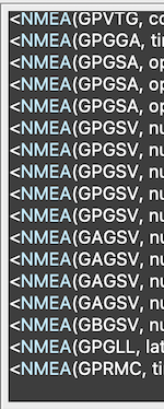
This will enable the IM19 NAVI ASCII NMEA-format GPFMI message on IM19 UART1. It contains the tilt-compensated pole tip position - once the IM19 is calibrated.

We need to set the LEVER_ARM, CLUB_VECTOR and INSTALL_ANGLE parameters carefully.

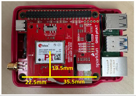
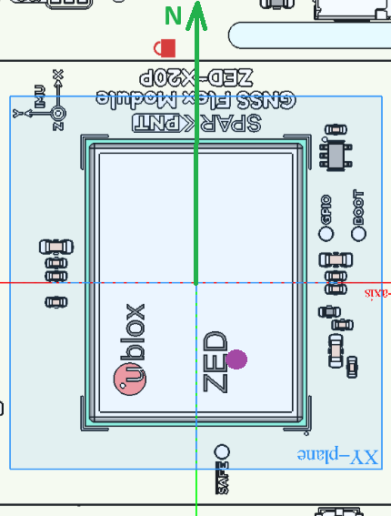
The X20P and IM19 module packages are centred on the centre of the Flex module. On the pHAT, the position relative to the mounting screw holes is:

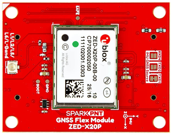
Important note: The IM19 IMU origin is not centred on the centre of the module. Using IMU Coordinates, it is offset by -5.72mm in X, and -2.72mm in Y. The green dot is the IMU origin:

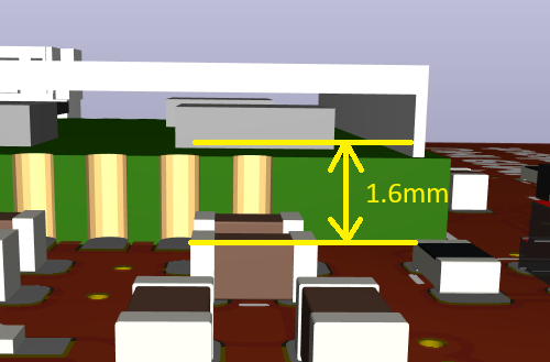
The IM19 Z origin is 1.6mm from the back surface of the Flex Module PCB:

In IMU Coordinates, the top surface of the Flex Module PCB is offset by +3.2mm in Z. 1.6mm for the PCB thickness plus the 1.6mm internal to the IM19.

The antenna reference position (phase centre) can be specified using either the LEVER_ARM=X,Y,Z message, or LEVER_ARM2=X,Y,Z. For LEVER_ARM2, note: “When setting the lever arm parameters by AT+LEVER_ARM2, the lever arm parameters will be internally rotated according to the currently installation angle. Therefore, the lever arm parameters should be measured in the default coordinate system of the module.” If the antenna is “above” the IMU, its Z position is negative for LEVER_ARM2, even though the IMU is flipped. The units are metres.

The CLUB_VECTOR=X,Y,Z message sets the pole length, from the ARP to the pole tip. The units are metres. For a 1.8m pole, the Z offset is +1.80m.

The INSTALL_ANGLE=X,Y,Z defines the rotation (installation angle) of the IMU package. Defining the rotation needs care if more than one rotation is involved. This video by u-blox is really useful here. The units are degrees. The IM19 manual says “Send AT+INSTALL_ANGLE=180,0,0 If the IM19 module is mounted on the back of the GNSS receiver (so the IM19 faces downward instead of upward)”. That is only true if the module has been flipped around the X axis only.

The IM19 manual says:

  • “Make sure the end of the RTK pole is placed on the ground and does not move. [Rock] the RTK pole back and forth for 2 to 3 times. The IM19 module will alter the positioning status to initialization complete, and the user can start tilt survey.”
  • “If the installation angle has not been calibrated in the factory, when initializing in the first time, you need to rotate the RTK pole by 90° according to the prompt given by IM19 to complete the initialization.”

PyGPSClient has a tool to analyze the GPFMI message Status field: View \ Show IMU Monitor. The calibration is complete when FixRIsOK is observed.

PyGPSClient can extract the Latitude, Longitude and Altitude from the GPFMI message. It is a fun thing to log data from both instances of PyGPSClient. The GNSS data contains the position of the antenna - with no tilt compensation. The IM19 GPFMI data contains the compensated pole tip position.

1 Like

In our Hookup Guide, we suggest adding the following to /boot/firmware/config.txt:

dtoverlay=uart0
dtoverlay=uart2,ctsrts
dtoverlay=uart3,ctsrts
dtoverlay=uart4

That would only be valid for the mosaic-X5 Flex module - which supports CTS and RTS handshaking. For the X20P, I recommend going with:

dtoverlay=uart0
dtoverlay=uart2
dtoverlay=uart3
dtoverlay=uart4
1 Like

From first power-up, the IM19 may need a AT+SYSTEM_RESET to kick it into action

Thanks for all the help. With the information you provided here, and with the working notes you sent privately, I am getting some results that look promising. Using two instances of PyGPSClient is very helpful, and pretty much essential.

This is my rover on a tripod:

The flange on the bottom is for a diamond saw or angle grinder that was easy to modify to attach a the cage I fabricated from 4 mm aluminum. The posts are just 1/4" bolts passing through some stainless steel tubing I salvaged from a discarded walkway light. The stack inside the cage is centered, and composed of a Waveshare UPS (E) and the other components I listed in the first comment.

I may have a sign error in my AT+LEVER_ARM2 setting. So far I’ve been testing with the rover mounted on a tripod that is significantly shorter than the 2 m pole I used for the AT+CLUB_VECTOR setting. The 2.1474 m includes the pole, 139.88 mm from base of flange to the base of the antenna reference point, and 7.53 mm to the mean APC offset from the ARP.

AT+CLUB_VECTOR=0,0,2.14741
AT+LEVER_ARM2=0.002372,0.000772,0.02929
AT+INSTALL_ANGLE=0,180,0

I used available CAD files to assemble a drawing in FreeCAD to determine the offsets for AT+LEVER_ARM2. The red lock is in this drawing is the axial center of the pole, component stack, and antenna. In the reference frame centered at the center of the ublox ZED, and aligned with the printed “IMU axes”, the axial center is at X=15 mm, Y=5 mm. I added the documented offsets from chip center to IMU origin to get the values LEVER_ARM2 X and Y. The Z value is based on the distance from the top of the Flex Module to the APC of 29.29 mm. (Looks like I forgot to add 3.2 mm to compensate for PC board and IMU thicknesses).

I’m not sure if I interpreted/specified the LEVER_ARM2 and INSTALL_ANGLE values correctly. I would appreciate feedback on how I set them.

Also, I never thought much about Roll, Pitch, and Yaw in this context. I guess the rover pole has a forward, left, and up directions. Up makes sense, but forward and left seem arbitrary. How do I use those values to check my setup?

Hi Steve (@steve.talent ),

Excellent. I’m glad the IM19 is starting to give you sensible results.

Looking at my notes with fresh eyes, I’m not convinced I got the LEVER_ARM2 settings correct. I’m going to check with Feyman (FMI), to make sure.

More later,
Paul

1 Like

For me, it helps to think in terms of a Static Session mission.
All geodetic antennas have a North arrow reference mark. This is so we can always align the Antenna to the North, so the electrical phase center (bias) corrections can be applied to the solution.

A similar concept applies to using Tilt Compensation. If the user always orients the antenna to the North (which is the standard procedure) and the IMU is aligned or compensated, then:

  • Roll = East/West offsets w/ consideration to the total Rod Height (trig)
  • Pitch = North/South offsets w/ consideration to the total Rod Height (trig)
  • Yaw = the (compass) bearing, which is not accurate and that’s an issue

With the precision afforded by RTK, we can calibrate the orientation of the device with intentional rocking over the point, but I don’t think SFE Firmware does that, IDK, never looked. But why not just plumb the rod correctly in that scenario with a bullseye bubble?

From my personal experience, tilt compensation causes more problems in the field than it solves. Sure, it can be extremely nice for 1% of your points, but it creates a unnecessary vulnerability for the other 99%. It’s a good example of an engineered solution looking for a problem in this industry.

That said, if it does solve a problem for you - maybe consider an aggressive feedback system to the user when it’s temporarily activated, something as obnoxious as a buzzer? That reminds the user that they need to pay special attention to the workflow for this point.

I failed to mention that I’m using a ublox ANN-MB2 antenna.

The datasheet shows the ARP at bottom center, and the Y-axis aligned with the cable. The mounting holes lie on the X-axis. In Section 5.2 Phase Center, they specify “North” is toward the cable connector.

The orientation of the antenna is such that North is aligned with the IMU Y-axis that is printed on top of the Flex Module. The axes of the antenna are oriented the same as the IMU axes printed on the top of Flex module.

Thanks for your feedback. I’m still learning. I have given some thought to adding a feedback system, but haven’t made any hard plans so far.

1 Like

I updated my IMU settings, but I’m not seeing any data in the IMU Monitor View of PyGPSClient. I see GPFMI messages in the Console which make sense, but I don’t know why they’re not showing up in the Monitor View. I’ll look at that later.

This reply is about the IMU configuration changes.

The documentation for setting AT+INSTALL_ANGLE=X,Y,Z is a bit ambiguous. The values represent rotations, but the order of how they are applied is not specified, and rotations are noncommutative. I used the AT+READ_PARA=SYSTEM command to read the Installation Matrix. Based on the IMU reference frame printed on the Flex Module, and how it aligns with the reference frame of my antenna, I needed to specify rotations that would invert the Z axis and swap X and Y axes. In other words, IMU Y should match Antenna “North”, which is the location of the cable connector. IMU X should then point East and Z should be down. In matrix representation:

Install Mat  : 0.000   1.000   0.000
               1.000   0.000   0.000
               0.000   0.000  -1.000

After some trial and error, I found this to be the correct setting to produce that result:

AT+INSTALL_ANGLE=180,0,90

I noticed that the Install Matrix would be printed to the output each time I tried a new setting, so it was not necessary to run the AT+READ_PARA=SYSTEM every time.

Hi Steve (@steve.talent ),

Thanks for the update.

Regarding the IMU Monitor View, there’s a trick in that you need to have NMEA ticked in “Protocols Shown”, and TTY unticked. If NMEA is unticked - or you have TTY ticked - you’ll see “No data available”.

I’m still talking to Feyman about IMU orientation and LEVER_ARM / INSTALL_ANGLE settings.

The IMU X,Y,Z axes are defined using the right hand coordinate system. For the body frame, they use Front-Right-Down. The simplest case is where X points Front, Y Right and Z Down. When X points North (in the North-East-Down reference frame), the Yaw angle is zero.

If you orient the pHAT so that X points North:

The IMU origin is roughly where I’ve place the magenta dot.

Feyman say that INSTALL_ANGLE should be sent first, then LEVER_ARM2.

The IMU faces down - rotated around X - so we should send:

AT+INSTALL_ANGLE=180,0,0

Then we should set LEVER_ARM2 using the default IMU coordinate system. Feyman say that with the Antenna to IMU offset as drawn, the X,Y and Z offsets are all positive. I had misunderstood this previously…

Working from the pixel scale of your screenshot and the position of the red lock symbol, I believe LEVER_ARM2 should be:

AT+LEVER_ARM2=0.0237,0.0050,0.0325

I’m expecting another update from Feyman on Monday. I’ve sent them five STEP files containing different antenna-IMU offsets and orientations, and have asked them to provide LEVER_ARM2 plus INSTALL_ANGLE for all five. I’ll post an update when I get their reply.

More later - all the best,
Paul

1 Like

Hi Paul (@PaulZC ),

Thanks for the update.

I mentioned using AT+READ_PARA=SYSTEM to see the Install Matrix. More information, including Lever Arm, is returned when using AT+READ_PARA=ALL. It even shows the temperature.

I need to fix my AT+LEVER_ARM2=X,Y,Z setting. My X and Y values were off by an order of magnitude. I will go back to my FreeCAD model to see if I can insert the dimensions into the drawing.

The ublox ANN-MB2 Data Sheet states that antenna “North” points toward the antenna connector. Because of the spacing of the antenna mounting holes, I needed to rotate the antenna in order to bolt it to the top of the cage I fabricated. In my case, North is aligned with the IMU Y axis so I have an additional 90 degree rotation around Z. Based on the alignment you show, I agree with your setting.

It appears that Feyman is applying the install angle rotations in X, Y, Z order. The conventional order is Z-Y-X. If the conventional order were used, the Z rotation would need to be 270 (or -90) in my case. I could be wrong here, but that’s what I suspect is happening.

Local weather forecast is calling for rain for the next several days, so I may have limited time to test.

Hi Steve (@steve.talent ),

I got a detailed reply from Feyman on the INSTALL_ANGLE and LEVER_ARM2 settings.

I’m attaching the five step files I sent to them plus their reply. It is a zip file, you will need to: download it, rename it to remove the “.txt” extension, and then unzip it.

IM19_LEVER_ARM2.zip.txt (2.1 MB)

For the Body Frame: The Red arrow points Front. The Green Arow points Right. The Blue Arrow points Down.

For the Reference Frame: The Body Front is pointing North. The Red Arrow points North. Green points East. Blue points Down.

In Configuration_1_FRD: The IM19 faces Up. IM19 X axis points Front / North. The antenna is 140mm above the IM19.

In Configuration_2_FRD: The IM19 is rotated around its Z axis. The X axis now points Right / East.

In Configuration_3_FRD: The IM19 is rotated around its X axis. The IM19 now faces Down. The X axis still points Right / East.

In Configuration_4_FRD: The IM19 is moved Left (West) by 75mm The X axis still points Right / East.

In Configuration_5_FRD: The IM19 is moved Back (South) by 50mm. The X axis still points Right / East.

Configuration 5 matches your pHAT assembly, when the IM19 Y axis points North.

I agree that your settings should be:

AT+INSTALL_ANGLE=180,0,90
AT+LEVER_ARM2=0.0237,0.0050,0.0325

or thereabouts…!

Very best wishes,
Paul

Tagging @semuadmin so he can follow the discussion

Sorry - one more thing:

Feyman confirmed that the reported Yaw should be the same for all five configurations.

Best,
Paul

Thanks @PaulZC ,

The drawings were very helpful.

I tagged your reply as the Solution, but the complete solution involves most of your posts.

Feyman documentation was not very clear. I was looking at “IM19 User Manual V 1.1” and “IM19 User Manual V 1.3.7”. It was not clear whether the IM19 origin was the corner of the package or the position of the MEMS unit within the package. I also noticed that the package size in the older manual was 16.4 x 14.8, but 18.4 x 14.8 in the later manual.

Your attached drawings verify that the IM19 “origin” is the location of the MEMS, which is offset from the package center at (-5.72,-2.72) or (-5.7,-2.7) as shown in your drawings (Section 2.4 of V 1.3.7 IM19 User Manual shows more precision).

I did discover something curious. I entered the following commands:

AT+INSTALL_ANGLE=180,0,90
AT+LEVER_ARM2=0.02372,0.00722,0.03249

When the second command was entered, the IM19 sent the response:

Lever Arm : 8.886e-03, 1.793e-02,-3.249e-02

Apparently there is an additional origin offset that is applied internally by the IM19 firmware. I don’t know why 7.22 mm was changed to 8.886 mm, nor why 23.72 mm was changed to 17.93 mm. I will just accept it as necessary :wink:

Now that my question has been resolved, I am ready to move on to the next steps. I need to add some kind of onboard feedback. So far I have been testing with PyGPSClient over VNC. I need a way to monitor the IM19 status so I can go through the initialization steps and keep track of Ready status.

Thanks again!

I had some success with the IM19 a week or so ago, but now it’s not working. I just noticed that the output from UART1 of the ZED-X20P is showing “GN” messages instead of “GP” messages.

I’m running PyGPSClient on both my base and rover and using NTRIP over my LAN’s WiFi.

I updated PyGPSClient a few days ago, and I’ve run into a couple of bugs, so I’m not sure if that is related.

Any ideas where I should start?

Hi steve.talent - what specific issues are you having with PyGPSClient in relation to this procedure? I’m not aware of any significant bugs with the latest 1.5.20.

FYI re. “GP” vs “GN” - this may be a “CFG-NMEA-MAINTALKERID” setting issue. “GN” is the traditional ‘talker’ for GNSS in general; “GP” refers specifically to the USA’s GPS constellation, as opposed to “GA” (Galileo), “GL” (GLONASS), etc. By default, the X20P will output “GN” but you can set CFG-NMEA-MAINTALKERID to 1 to force it to use “GP” instead:

(This provision is a throwback to the original NMEA 2.n protocol which pre-dated the current multiplicity of GNSS constellations)

Note: this only applies to the X20P - the IM19 should only ever output GPFMI, e.g.

Hi Steve (@steve.talent ),

I’d recommend checking your NTRIP connection, and making sure that your Rover is in RTK Fix. The tilt compensation won’t work without RTK Fix.

I don’t recall needing to change the Talker ID. I believe the IM19 is agnostic on GN vs GP.

I hope this helps,
Paul

That was my expectation as well - but just wanted to mention it as a possibility.