Help with Qwiic Boost

I got a couple of the Qwiic Boost (SPX -17238) to help me connect the Sensirion Particulate Matter Sensor - SPS30 which requires a 5V power input. The description for the qwiic boost says:

For applications where the 5V device needs 5V I2C signals, a conversion circuit is provided with the board. A jumper is available to select between 3.3V (default) and 5V I2C signals.

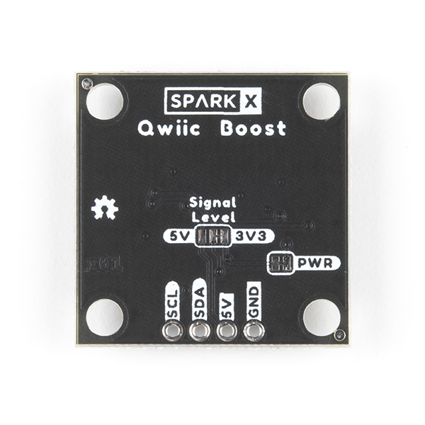
I can’t seem to find that jumper. Support says its on the back but I really can’t find it !

Also want to verify if the qwiic boost has an onboard pull-up resistor (10K), which the SPS30 also needs ?

Thanks for reaching out to us on this.

Read through this article on pull-up resistors https://learn.sparkfun.com/tutorials/pu … 1615791300 to get a better understanding of how they function, and then do the same for jumper pads https://learn.sparkfun.com/tutorials/ho … pcb-traces

Here is a photo of the selectable jumper on the back of the board https://cdn.sparkfun.com//assets/parts/ … ost-03.jpg - you will know how to use this after reading those articles.

Finally, here is the schematic for the resistors https://cdn.sparkfun.com/assets/f/a/e/d … ematic.pdf

Hope this helps, and happy sparking!

The jumpers are labeled “signal level” and “pwr” on the back of the board.

@YellowDog - Do i have to modify both jumpers in this case or just the one labled “signal level”?

@TS-Russell - thanks for the guides. I guess I will learn something new by doing this. But you didnt say if the boost already has an inbuilt pull up or if I need to use an external one ?

Do i have to modify both jumpers in this case or just the one labled “signal level”?

If you want to turn the LED off, yes. Otherwise, no.

You might want to refer to the [schematic so that you know what you’re modifying.](https://cdn.sparkfun.com/assets/f/a/e/d/3/Qwiic_Boost_Schematic.pdf)