I just rec’d the Sparkx inline panel meter SPX-18571, fully expecting some sort of documentation to come with it, at the bare minimum a schematic, so I could put it together, since there is nothing on the website except some links to GitHub to some sch files which display as garbage.
I know Sparkx products are supposed to come without such but really, Sparkfun, this is below what is acceptable for selling something, especially something that needs to be put together. We all know circuits are pretty much useless without schematics and this is Exhibit A of something like that.
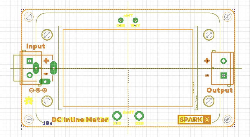
If your male connector is center-positive, it looks like it’d be black to sleeve, red to tip, white to signal…then just red to pos and black to neg on the other side
I do not use Eagle. I use DipTrace. At any rate, I cluttered up my computer with the 131 MB installation file, followed by 1653 files totally 579 MB of installed stuff, for something I will never otherwise use, and tried to open the SCH file with it but it claims it is invalid format. So I’m still no farther ahead.
In DipTrace I can create a PDF of a schematic with a couple of mouse clicks, so I assume that can be done in eagle too. Why can’t you just put a universally readable PDF schematic for it on your website, like you do with most things you sell?
I’ve bought hundreds of things from Sparkfun, designed and had fabricated hundreds of PCB’s (including with the service you used to run) and program several different types of microcontrollers in assembly, C, C++, arduino and MicroPython, for the past 20 years or more. Simple as the meter may be, I still need a schematic for it. Wire colors don’t tell me anything about how it works, or electrically what the connections are, or how I can modify the connections, etc.