Hi not sure if you can help I have this servo trigger built into a ghostbusters pke meter all good but I’m trying to fit a working emf meter into it but the emf board is 9v with leds and when I connect the triggers signal wires it powers up constantly but I want the led to light then move the servo any idea what I need to achieve this many thanks
Maybe share a diagram/photo of what you’re up to


So basically ive built the pke meter from ghostbusters but wanted it to actually work as an emf meter so ive bought a emf meter off amazon but when i connect the servo trigger wires to the emf board it powers the servos but i want to servos to only work when the 3rd or 4th led lights up if that makes sense lol
Ah
I think you can get it done by testing the 1st photo’s circuit board while in-use…you need to figure out what part of the circuit is active when you want it triggered (3/4th LED?)…and then solder a wire from that circuit to the servo trigger’s input. The servo trigger doesn’t list a minimum voltage, so test what the black board is outputting (5.5v max, LED circuits are usually 2.x-3.x volts, so you might have to use a step-up converter if the voltage isn’t enough to trigger the servo trigger).
Hopefully the other LEDs in the meter stay on the make your life easier (like, when @ level 4/orange the previous 3 LEDs (green, green, yellow) are lit up as well so that the servo trigger will remain triggered). If only one LED is active at a time you might have to wire it to them individually
Ah ok i see thankyou i will give that a go and see what happens the board is 9 volts so ive installed a power reducing board to 5volts for the servos a servo trigger board
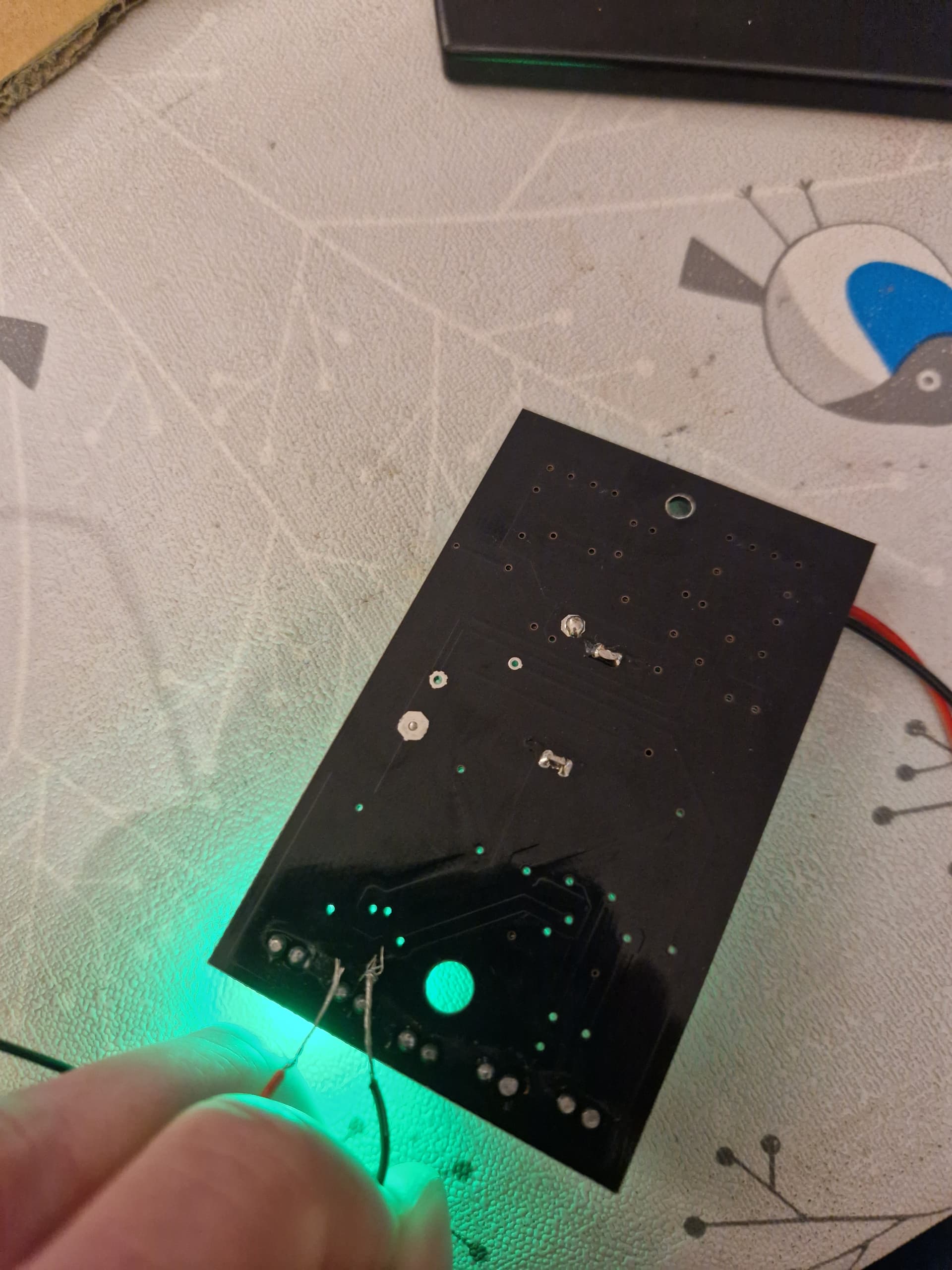
Yep, I saw that ![]() For clarity, what I mean is you might have to do the opposite if the voltage from the black circuit is too low to drive the trigger board…you’ll have to test it and see
For clarity, what I mean is you might have to do the opposite if the voltage from the black circuit is too low to drive the trigger board…you’ll have to test it and see
I think ive been looking at this wrong ive been putting the trigger wires to an led where you normall have a switch to activate the board are you saying connect the power wires of the board to the led and bump up the voltage to no more than 5v
No, you’re thinking about it right. You’ll only need to step up the output from the LED going to SIG on the trigger board IF it doesn’t work as-is
Hi sorry to keep asking lol ive put the signal wires to an led to test the servos kick in but stay up and all the other leds go off is like its drawing power from the trigger board would some sort of resistor inbetween work somehow sorry to keep asking
There should only be 1 wire coming from the LED to SIG…share a photo


I have 2 wires out of the servo trigger for a switch ect ive put these on positive and negative of the emf board for the led the servos work but it just keeps the led on the others stop working and servos dont go back down if that makes sense
Sorry think i had a brain block i was using the trigger wires not the yellow signal wire so connected the yellow signal wire to the led didnt move so how do i up the voltage from the led its running a 9 volt battery do i need a step up converter off off the led to signal wire thanks again
Yes, a step-up converter from the LED from whatever it is (probably 2.5-3.5v) up to 5v. Wire the Black/GND on the step-up to any ground on the LED board (or the leg of the LED!) and you should be all set
Lovely will order one up thankyou so much for your help no idea why i didnt come on here sooner thanks