I am trying to set up SparkFun JetBot AI Kit with NVIDIA Jetson Nano.
I am not able to run the 1st experiment called Basic motion through python notebook.
I have made sure the soldering is correct on the motor driver board, I can see red LED blinking every 2.5 seconds (working normally).
The connection from Micro OLED to motor driver is correct (Yellow to “SCL,” Blue to “SDA,” Black to “GND”)
I also tested motors separately (They work by powering through my AA batteries)
I don’t get any errors while initializing the robot and calling methods right and left by passing speed arguments. It’s just that the robot doesn’t do anything.
Can somebody help how can I debug my setup ?
There’s a few jumpers that need set on the motor controller PCB for the motor driver to be able to communicate with the Jetson.
Make sure you have the board configured the way we show in the [hookup guide and that you’re using our SD card image and your motors should begin working. 
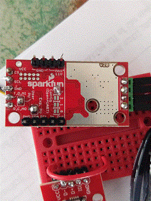
If you’re still having trouble after checking those items, send a photo of the top and bottom of your motor driver board so we can have a look.](Assembly Guide for SparkFun JetBot AI Kit - SparkFun Learn)
I have same issues on post “Jetson JetBot AI Kit - Issues with qwiic IC2”.
I set configuration bits on the motor drive " bridge pad 3". And also, I solder two jumpers are just for the pull-up resistors.
it still don’t move
Do you have any ideal to debug ?
Let’s begin with Chris’ questions:
- Are you following the [[hookup guide](https://learn.sparkfun.com/tutorials/assembly-guide-for-sparkfun-jetbot-ai-kit/) and are you using [[ our Jetbot image](https://static.sparkfun.com/large/sparkfun_jetbot_v01-00.zip) for our version of the kit?
Here are a few follow up questions, I also have:
- If you are, please specify that; otherwise, I would begin with the hookup guide to get the motor driver operational.
- If you are, can you send pictures of your setup?
- If you are... I don't remember if the Jupyter notebook examples are written in a way that they would throw an error. However, could you send a screenshots of the cells being executed and describe in more detail what response you are seeing from the Jetbot and where the issue is?
[/list]
Here are a few additional items you may want to doublecheck:
- I would double check your power connections for the motors to the motor driver.
- I did notice that sometimes the notebook examples get hung up, are you sure it isn't the notebook freezing?
- If so, you might need to restart the jetson nano and/or clear the notebook with a *kernel restart* (under **Kernel** tab).
](https://static.sparkfun.com/large/sparkfun_jetbot_v01-00.zip)](https://learn.sparkfun.com/tutorials/assembly-guide-for-sparkfun-jetbot-ai-kit/)
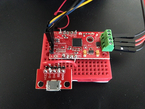
![]() pic1
pic1
![]() pic2
pic2
if plug motor drive to pHat or back of Oled display. motor don’t move and OLED don’t work.
unplug motor drive from pHat or OLED display. OLED display work. it display ip address, CPU. I can send display command to OLED display.
only plug motor drive to pHat. unplug OLED display. motor still don’t move.
Do you have any idea ?

Unfortunately, it is difficult to troubleshoot your issue without complete responses to the questions I laid out. Please, answer them fully with screenshots, so that I can provide further assistance.
However, if I had to guess… it sounds like you might not have the serial controlled motor driver powered through the USB jack before connecting it to the I2C bus or when powering the Jetson, “on” (as shown in the hookup guide). That would be the primary cause for the OLED to be working and then stop after you attach the SCMD.
Also, I can’t really tell from the image quality (try using a .jpeg instead of a .gif file), but double check your soldering connections to make sure that you have secure electrical connections.
![]() pic1
pic1
![]() pic2
pic2
I following your hookup guide. and also, I used sparkfun jetbot image.
I did check all connection. serial controlled motor driver powered through the USB jack.
if motor driver connect to I2C bus, oled display will show nothing.
And also, I use terminal to type those command .
→ python3
→ from jetbot import Robot
→ robot = Robot()
→ robot.left(speed=0.3)
nothing happened. I don’t see any error from terminal . “robot.left” take more than 5 min to return nothing.
Do you have any idea ?

I tested a fresh image and the libraries for the jetbot and SCMD seem to be working fine.
- I normally prefer to troubleshoot with the examples that Nvidia provides (like the basic_motion notebook) as they have been tested to work. However, I tried the steps you mentioned and there were no code issues. Also, there is not output from the code so you shouldn't expect a response back.
- Since this doesn't seem to be a software related issue, it is likely a hardware problem in your setup.
To begin troubleshooting the hardware, let’s narrow down a few things first:
- I need pictures of your board/soldering again. I am trying to inspect the soldering, but the .gif files are noisy, low resolution images that are making it challenging.
- Please, do not use .gif files... their image quality is extremely poor. (*GIFs are primarily used to convert videos into small frame rate images with small file sizes. To achieve this, the image quality is extremely reduced.*)
- Please, use another file type like a .jpeg, .png, etc. with a higher quality, higher resolution image. Thank you.
- Where is the power for the SCMD coming from (battery pack (what is the power output rating?), jetson, etc.)? Please send a picture of how it is being powered.
- Let's ping the device. Only attach the SCMD and use, "**i2cdetect -y -r 1**", in the terminal.
- You should see a table with **0x5D** listed.
- Otherwise, it means there is a connection issue on the I2C bus or the device isn't powered. Try swapping the Qwiic cabled to verify if it is a faulty cable.
- If the device is listed, lets check the configuration. Use, "**i2cdump -y 1 0x5d**", in the terminal.
- You should see a table with the values stored in the registers. Please send a screen shot of this.
- Let's double check the wiring to make sure that the motors are paired properly.
- One motor should be connected to **A1** + **A2**.
- The other motor should be connected to **B1** + **B2**.


