Hi,
I’m using the Spark Fun Bi-directional Logic Level Converter (BOB-12009) and wondering about the ground. I have this wired matching the tutorial with two separately powered microcontrollers, one 3.3V and the other 5.5V. It works great, stepping-up and down the voltage as needed. But I noticed the ground pins on the breakout board are connected through a trace. That is, attaching my DMM shows continuity between the “High Side” and “Low Side” ground pins. I obviously don’t understand how this works, as I would suspect connecting the two grounds would cause a ground loop and possibly fry one of the devices due to the drop.
I would appreciate it if someone could either explain this to me, or point me to somewhere I could learn more.
Thanks
The two MCUs must have a common ground for the logic level converter to work.
There is usually no reason to be concerned about a “ground loop”, unless you have equipment powered by different branches of an AC power distribution panel, or very long power leads connecting the MCUs. In those cases, use optocouplers for data transmission.
For more complete analysis, post a wiring diagram of your project, showing how everything is powered and connected.
Adding to what @jremington stated; the logic level converter is designed to work on systems at the same ground potential. If you have systems that need separate ground potential, that logic converter design is not what you are looking for (you should be looking for a type of isolator - e.g. opto-isolator, transformer, etc).
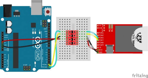
Thank you both for the detailed replies. I can’t upload a wiring diagram due to NDAs, but the diagram is an exact match of the demo seen with the below link except I’m using an breadboarded atMega328P (not an Ardunio) and a custom ASIC on the other side.
https://cdn.sparkfun.com/r/600-600/asse … lFixed.png
I’m using a dual rail power supply supplying both voltages (5 and 3Vs), both floating. I was not familiar with opto-isolators, very interesting and worth a look!
Thanks for your help, it is very much appreciated. I’m a computer engineer playing an electrical engineer 
The negative leads of the 5V and 3V supplies must be connected together (as common ground) for the logic level converter to work.