Hi All,
I think I’ve seen something about this in the docs somewhere, but I can’t seem to find it now!
Is it possible to create text (for pin names, wire labels, etc.) that have the negation bar over the text? I can do something like ‘*MCLR’ for example to indicate thata signal is active-low, but it would be so much nicer to be able to write the text with a bar over the top!
Thanks,
John
John,
Placing an exclamation mark before and after your text, such as !MCLR!, will do what you want.
Jon
Hi Jon,
Ah!, perfect, that works like a charm  !
!
Thanks,
John
Along those lines, how do we add symbols, like a diode symbol, to the silk screen?
how do we add symbols, like a diode symbol, to the silk screen?
You draw them, using lines, rectangles, arcs, polygons, and etc. usually within the library part definition for the relevant component. For instance, I got tired of not being able to tell my SMT resistors from my SMT capacitors and made new separate packages:
[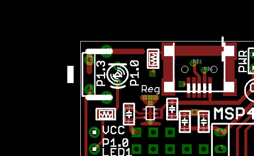 <LINK_TEXT text=“http://farm4.static.flickr.com/3341/570 … fe63db.jpg”>http://farm4.static.flickr.com/3341/5708838055_a36afe63db.jpg</LINK_TEXT>
You have to pay some attention to how much will show on the actual PCB, once the silkscreen layers are clipped to the non-exposed-copper areas (xCream), and you can be exacting about putting some of the drawing on tPlace (actual silkscreen, usually) and some on tDocu (only shown in editor) if you want…](modifiedRCL | Note that R & C component packages have been m… | Flickr)